Intel E2160 Design Guide - Page 23
Processor Thermal Solution Performance Assessment - chipset
 |
UPC - 735858199216
View all Intel E2160 manuals
Add to My Manuals
Save this manual to your list of manuals |
Page 23 highlights
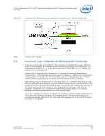
Thermal Metrology-Intel® CoreTM 2 Duo E6400, E4300, and Intel® Pentium® Dual-Core E2160 Processor 3.2 3.3 To determine the required heatsink performance, a heatsink solution provider would need to determine CS performance for the selected TIM and mechanical load configuration. If the heatsink solution were designed to work with a TIM material performing at CS 0.10 °C/W, solving for Equation 2 from above, the performance of the heatsink would be: ΨSA = ΨCA - ΨCS = 0.29 - 0.10 = 0.19 °C/W Processor Thermal Solution Performance Assessment Thermal performance of a heatsink should be assessed using a thermal test vehicle (TTV) provided by Intel. The TTV is a stable heat source for making accurate power measurements, whereas processors can introduce additional factors that can impact test results. In particular, the power level from actual processors varies significantly, even when running the maximum power application provided by Intel, due to variances in the manufacturing process. The TTV provides consistent power and power density for thermal solution characterization and results can be easily translated to real processor performance. Accurate measurement of the power dissipated by an actual processor is beyond the scope of this document. Once the thermal solution is designed and validated with the TTV, it is strongly recommended to verify functionality of the thermal solution on real processors and on fully integrated systems The Intel maximum power application enables steady power dissipation on a processor to assist in this testing. This application is called the Maximum Power Program for the Intel® Core™ 2 Duo Processor. Contact your Intel Field Sales representative for a copy of the latest release of this application. Local Ambient Temperature Measurement Guidelines The local ambient temperature TA is the temperature of the ambient air surrounding the processor. For a passive heatsink, TA is defined as the heatsink approach air temperature; for an actively cooled heatsink, it is the temperature of inlet air to the active cooling fan. It is worthwhile to determine the local ambient temperature in the chassis around the processor to understand the effect it may have on the case temperature. TA is best measured by averaging temperature measurements at multiple locations in the heatsink inlet airflow. This method helps reduce error and eliminate minor spatial variations in temperature. The following guidelines are meant to enable accurate determination of the localized air temperature around the processor during system thermal testing. For active heatsinks, it is important to avoid taking a measurement in the dead flow zone that usually develops above the fan hub and hub spokes. Measurements should be taken at four different locations uniformly placed at the center of the annulus formed by the fan hub and the fan housing to evaluate the uniformity of the air temperature at the fan inlet. The thermocouples should be placed approximately 3 mm to 8 mm [0.1 to 0.3 in] above the fan hub vertically and halfway between the fan hub and the fan housing horizontally as shown in Figure 5 (avoiding the hub spokes). Using an open bench to characterize an active heatsink can be useful, and usually ensures more uniform temperatures at the fan inlet. However, additional tests that include a solid barrier above the test motherboard surface can help evaluate the potential impact of the chassis. This barrier is typically clear Plexiglas*, extending at least 100 mm [4 in] in all directions beyond the edge of the thermal solution. Typical distance from the motherboard to the barrier is 81 mm [3.2 in]. For an even more realistic airflow, the motherboard should be populated with significant elements like memory cards, a graphic card and a chipset heatsink. If a barrier is used, the thermocouple can be taped directly to the barrier with clear tape at the horizontal location as previously described, October 2007 Order Number: 315279 - 003US Intel® CoreTM 2 Duo E6400, E4300, and Intel® Pentium® Dual-Core E2160 Processor TDG 23
-
 1
1 -
2
-
3
-
4
-
5
-
6
-
7
-
8
-
9
-
10
-
11
-
12
-
13
-
14
-
15
-
16
-
17
-
 18
18 -
 19
19 -
 20
20 -
 21
21 -
 22
22 -
 23
23 -
 24
24 -
 25
25 -
 26
26 -
 27
27 -
 28
28 -
29
-
30
-
31
-
32
-
33
-
34
-
35
-
36
-
37
-
38
-
39
-
40
-
41
-
42
-
43
-
44
-
45
-
46
-
47
-
48
-
49
-
50
-
51
-
52
-
53
-
54
-
55
 |
 |
