Intel E2160 Design Guide - Page 27
PROCHOT# Signal, 4.2.2 Thermal Control Circuit
 |
UPC - 735858199216
View all Intel E2160 manuals
Add to My Manuals
Save this manual to your list of manuals |
Page 27 highlights
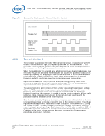
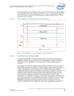
Thermal Management Logic and Thermal Monitor Feature-Intel® CoreTM 2 Duo E6400, E4300, and Intel® Pentium® Dual-Core E2160 Processor 4.2.1 Note: 4.2.2 PROCHOT# Signal The primary function of the PROCHOT# signal is to provide an external indication that the processor has exceeded its maximum operating temperature. While PROCHOT# is asserted, the TCC will be active. Assertion of the PROCHOT# signal is independent of any register settings within the processor. It is asserted any time the processor die temperature reaches the trip point. PROCHOT# can be configured via BIOS as an output or bi-directional signal. As an output, PROCHOT# will go active when the processor temperature of either core exceeds its maximum operating temperature. This indicates that the TCC has been activated. As an input, assertion of PROCHOT# will activate the TCC for both cores. The TCC will remain active until the system de-asserts PROCHOT#. The temperature at which the PROCHOT# signal goes active is individually calibrated during manufacturing. The power dissipation of each processor affects the set point temperature. The temperature where PROCHOT# goes active roughly parallels the thermal profile. Once configured, the processor temperature at which the PROCHOT# signal is asserted is not re-configurable. One application of using PROCHOT# is the thermal protection of voltage regulators (VR). System designers can create a circuit to monitor the VR temperature and activate the TCC when the temperature limit of the VR is reached. By asserting PROCHOT# (pulled-low) or FORCEPR#, which activates the TCC, the VR can cool down as a result of reduced processor power consumption. Bi-directional PROCHOT# can allow VR thermal designs to target maximum sustained current instead of maximum current. Systems should still provide proper cooling for the VR, and rely on a bi-directional PROCHOT# signal only as a backup in case of system cooling failure. A thermal solution designed to meet the thermal profile targets should rarely experience activation of the TCC as indicated by the PROCHOT# signal going active. Thermal Control Circuit The Thermal Control Circuit portion of the Thermal Monitor must be enabled for the processor to operate within specifications. The Thermal Monitor's TCC, when active, will attempt to lower the processor temperature by reducing the processor power consumption. In the original implementation of thermal monitor this is done by changing the duty cycle of the internal processor clocks, resulting in a lower effective frequency. When active, the TCC turns the processor clocks off and then back on with a predetermined duty cycle. The duty cycle is processor specific, and is fixed for a particular processor. The maximum time period the clocks are disabled is ~3 μs. This time period is frequency dependent and higher frequency processors will disable the internal clocks for a shorter time period. Figure 7 illustrates the relationship between the internal processor clocks and PROCHOT#. Performance counter registers, status bits in model specific registers (MSRs), and the PROCHOT# output pin are available to monitor the Thermal Monitor behavior. October 2007 Order Number: 315279 - 003US Intel® CoreTM 2 Duo E6400, E4300, and Intel® Pentium® Dual-Core E2160 Processor TDG 27
-
 1
1 -
2
-
3
-
4
-
5
-
6
-
7
-
8
-
9
-
10
-
11
-
12
-
13
-
14
-
15
-
16
-
17
-
18
-
19
-
20
-
21
-
 22
22 -
 23
23 -
 24
24 -
 25
25 -
 26
26 -
 27
27 -
 28
28 -
 29
29 -
 30
30 -
 31
31 -
 32
32 -
33
-
34
-
35
-
36
-
37
-
38
-
39
-
40
-
41
-
42
-
43
-
44
-
45
-
46
-
47
-
48
-
49
-
50
-
51
-
52
-
53
-
54
-
55
 |
 |
