Intel E2160 Design Guide - Page 29
Operation and Configuration, Thermal Monitor 2 Frequency and Voltage Ordering - driver
 |
UPC - 735858199216
View all Intel E2160 manuals
Add to My Manuals
Save this manual to your list of manuals |
Page 29 highlights
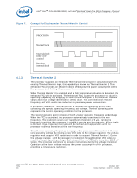
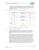
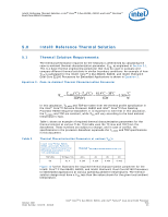
Thermal Management Logic and Thermal Monitor Feature-Intel® CoreTM 2 Duo E6400, E4300, and Intel® Pentium® Dual-Core E2160 Processor Figure 8. Once the processor has sufficiently cooled, and a minimum activation time has expired, the operating frequency and voltage transition back to the normal system operating point. Transition of the VID code will occur first, in order to insure proper operation once the processor reaches its normal operating frequency. Refer to Figure 8 for an illustration of this ordering. Thermal Monitor 2 Frequency and Voltage Ordering T TM2 Temperature 4.2.4 PROCHOT# f MAX f TM2 Frequency VID VID TM2 VID Time Refer to the datasheet for more information on Thermal Monitor 2. Operation and Configuration To maintain compatibility with previous generations of processors, which have no integrated thermal logic, the Thermal Control Circuit portion of Thermal Monitor is disabled by default. During the boot process, the BIOS must enable the Thermal Control Circuit. Thermal Monitor must be enabled to ensure proper processor operation. The Thermal Control Circuit feature can be configured and monitored in a number of ways. OEMs are required to enable the Thermal Control Circuit while using various registers and outputs to monitor the processor thermal status. The Thermal Control Circuit is enabled by the BIOS setting a bit in an MSR (model specific register). Enabling the Thermal Control Circuit allows the processor to attempt to maintain a safe operating temperature without the need for special software drivers or interrupt handling routines. When the Thermal Control Circuit has been enabled, processor power consumption will be reduced after the thermal sensor detects a high temperature, i.e., PROCHOT# assertion. The Thermal Control Circuit and PROCHOT# transitions to inactive once the temperature has been reduced below the thermal trip point, although a small time-based hysteresis has been included to prevent multiple PROCHOT# transitions around the trip point. External hardware can monitor PROCHOT# and generate an interrupt whenever there is a transition from active-toinactive or inactive-to-active. PROCHOT# can also be configured to generate an October 2007 Order Number: 315279 - 003US Intel® CoreTM 2 Duo E6400, E4300, and Intel® Pentium® Dual-Core E2160 Processor TDG 29
-
 1
1 -
2
-
3
-
4
-
5
-
6
-
7
-
8
-
9
-
10
-
11
-
12
-
13
-
14
-
15
-
16
-
17
-
18
-
19
-
20
-
21
-
22
-
23
-
 24
24 -
 25
25 -
 26
26 -
 27
27 -
 28
28 -
 29
29 -
 30
30 -
 31
31 -
 32
32 -
 33
33 -
 34
34 -
35
-
36
-
37
-
38
-
39
-
40
-
41
-
42
-
43
-
44
-
45
-
46
-
47
-
48
-
49
-
50
-
51
-
52
-
53
-
54
-
55
 |
 |
