Konica Minolta magicolor 7450 II grafx magicolor 7450 II User Guide - Page 217
PRINT MENU/CONFIGURATION PG, Declare the additional RAM in the Windows printer driver Properties/Con
 |
View all Konica Minolta magicolor 7450 II grafx manuals
Add to My Manuals
Save this manual to your list of manuals |
Page 217 highlights
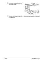
3 Insert the new DIMM straight into the DIMM connector until the latches snap into the locked position. Observe the keyed side of the DIMM to align it with the connector. If you cannot snap the DIMM into place, do not force it. Reposition it, making sure that the DIMM is seated completely in the connector. 4 Attach the left-side cover and tighten the screws. 5 Reconnect all interface cables. 6 Reconnect the power cord, and turn on the printer. 7 Declare the additional RAM in the Windows printer driver (Properties/Con- figure tab). 8 Print a configuration page (PRINT MENU/CONFIGURATION PG) and verify that the total amount of the RAM installed in your printer is listed. Dual In-Line Memory Module (DIMM) 203
-
 1
1 -
2
-
3
-
4
-
5
-
6
-
7
-
8
-
9
-
10
-
11
-
12
-
13
-
14
-
15
-
16
-
17
-
18
-
19
-
20
-
21
-
22
-
23
-
24
-
25
-
26
-
27
-
28
-
29
-
30
-
31
-
32
-
33
-
34
-
35
-
36
-
37
-
38
-
39
-
40
-
41
-
42
-
43
-
44
-
45
-
46
-
47
-
48
-
49
-
50
-
51
-
52
-
53
-
54
-
55
-
56
-
57
-
58
-
59
-
60
-
61
-
62
-
63
-
64
-
65
-
66
-
67
-
68
-
69
-
70
-
71
-
72
-
73
-
74
-
75
-
76
-
77
-
78
-
79
-
80
-
81
-
82
-
83
-
84
-
85
-
86
-
87
-
88
-
89
-
90
-
91
-
92
-
93
-
94
-
95
-
96
-
97
-
98
-
99
-
100
-
101
-
102
-
103
-
104
-
105
-
106
-
107
-
108
-
109
-
110
-
111
-
112
-
113
-
114
-
115
-
116
-
117
-
118
-
119
-
120
-
121
-
122
-
123
-
124
-
125
-
126
-
127
-
128
-
129
-
130
-
131
-
132
-
133
-
134
-
135
-
136
-
137
-
138
-
139
-
140
-
141
-
142
-
143
-
144
-
145
-
146
-
147
-
148
-
149
-
150
-
151
-
152
-
153
-
154
-
155
-
156
-
157
-
158
-
159
-
160
-
161
-
162
-
163
-
164
-
165
-
166
-
167
-
168
-
169
-
170
-
171
-
172
-
173
-
174
-
175
-
176
-
177
-
178
-
179
-
180
-
181
-
182
-
183
-
184
-
185
-
186
-
187
-
188
-
189
-
190
-
191
-
192
-
193
-
194
-
195
-
196
-
197
-
198
-
199
-
200
-
201
-
202
-
203
-
204
-
205
-
206
-
207
-
208
-
209
-
210
-
211
-
 212
212 -
 213
213 -
 214
214 -
 215
215 -
 216
216 -
 217
217 -
 218
218 -
 219
219 -
 220
220 -
 221
221 -
 222
222 -
223
-
224
-
225
-
226
-
227
-
228
-
229
-
230
-
231
-
232
-
233
-
234
-
235
-
236
-
237
-
238
-
239
-
240
-
241
-
242
-
243
-
244
-
245
-
246
-
247
-
248
-
249
-
250
-
251
-
252
 |
 |

Dual In-Line Memory Module (DIMM)
203
3
Insert the new DIMM straight
into the DIMM connector until
the latches snap into the locked
position.
Observe the keyed side of the
DIMM to align it with the connec-
tor. If you cannot snap the DIMM
into place, do not force it. Repo-
sition it, making sure that the
DIMM is seated completely in
the connector.
4
Attach the left-side cover and tighten the screws.
5
Reconnect all interface cables.
6
Reconnect the power cord, and
turn on the printer.
7
Declare the additional RAM in the Windows printer driver (Properties/Con-
figure tab).
8
Print a configuration page (
PRINT MENU/CONFIGURATION PG
) and
verify that the total amount of the RAM installed in your printer is listed.