Lantronix XPress-DR XPress-DR / XPress-DR-IAP - User Guide - Page 21
Screw-Terminal Serial Connectors, Table 2 - Serial Screw-Terminal Pinouts
 |
View all Lantronix XPress-DR manuals
Add to My Manuals
Save this manual to your list of manuals |
Page 21 highlights
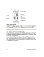
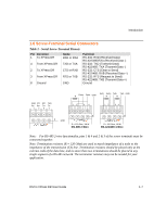
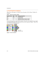
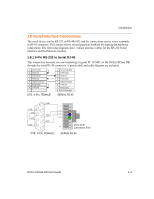
Introduction 1.6 Screw-Terminal Serial Connectors Table 2 - Serial Screw-Terminal Pinouts Pin Direction 1 To XPress DR 4 From XPress DR 2 To XPress DR 3 From XPress DR 8 Ground Name RXD or RXA TXD or TXA CTS or RXB RTS or TXB GND Function RS-232: RXD (Received Data) RS-422/485:RXA (Received Data -) RS-232: TXD (Transmit Data) RS-422/485: TXA (Transmit Data -) RS-232: CTS (Clear to Send) RS-422/485: RXB (Received Data +) RS-232: RTS (Request to Send) RS-422/485: TXB (Transmit Data +) Ground RXD CTS RTS TXD Rx- Rx+ Tx+ Tx- 1234 8 GND R Data+ Data- GND RxD- RxD+ TxD+ TxD- GND R R 12 34 12 34 8 R = 120 Ohm, 1/8 W RS-485 2-Wire 8 R = 120 Ohm, 1/8 W RS-422/485 4-Wire Note: For RS-485 2-wire functionality, pins 1 & 4 and 2 & 3 of the screw terminals must be connected together. Note: Termination resistors (R = 120 Ohm) are used to match impedance of a node to the impedance of the transmission (TX) line. Termination resistors should be placed only at the extreme ends of the data line, and no more than two terminations should be placed in any single segment of a RS-485 network. The terminator resistors may not be needed for your application. DSTni-XPress DR User Guide 1-7
-
 1
1 -
2
-
3
-
4
-
5
-
6
-
7
-
8
-
9
-
10
-
11
-
12
-
13
-
14
-
15
-
 16
16 -
 17
17 -
 18
18 -
 19
19 -
 20
20 -
 21
21 -
 22
22 -
 23
23 -
 24
24 -
 25
25 -
 26
26 -
27
-
28
-
29
-
30
-
31
-
32
-
33
-
34
-
35
-
36
-
37
-
38
-
39
-
40
-
41
-
42
-
43
-
44
-
45
-
46
-
47
-
48
-
49
-
50
-
51
-
52
-
53
-
54
-
55
-
56
-
57
-
58
-
59
-
60
-
61
-
62
-
63
-
64
-
65
-
66
-
67
-
68
-
69
-
70
-
71
-
72
-
73
-
74
-
75
-
76
-
77
-
78
-
79
-
80
-
81
-
82
-
83
-
84
-
85
-
86
-
87
-
88
-
89
-
90
-
91
-
92
-
93
-
94
-
95
-
96
-
97
-
98
-
99
-
100
-
101
-
102
-
103
-
104
-
105
-
106
-
107
-
108
-
109
-
110
-
111
-
112
-
113
-
114
-
115
-
116
-
117
-
118
-
119
-
120
-
121
-
122
-
123
-
124
-
125
-
126
-
127
-
128
-
129
-
130
-
131
-
132
-
133
-
134
-
135
-
136
-
137
-
138
-
139
-
140
-
141
-
142
-
143
-
144
-
145
-
146
-
147
-
148
-
149
 |
 |
