Lantronix XPress-DR XPress-DR / XPress-DR-IAP - User Guide - Page 22
RJ-45 Ethernet Interface, Table 3 - Ethernet Interface Signals, RJ-45 Connector
 |
View all Lantronix XPress-DR manuals
Add to My Manuals
Save this manual to your list of manuals |
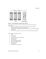
Page 22 highlights
Introduction 1.7 RJ-45 Ethernet Interface DSTni-XPress DR supports 10/100Mbit Ethernet through its RJ-45 (10BaseT/100BaseTX) connector. Table 3 - Ethernet Interface Signals Signal Name DIR TX+ Out TX- Out RX+ In RX- In PIN Primary Function 1 Transmit Data + 2 Transmit Data 3 Differential Ethernet Receive Data + 6 Differential Ethernet Receive Data - The next drawing shows a typical RJ-45 connector. The color is not standard but very typical of an Ethernet Patch cable. Pin 1 is located at the top of the connector (Orange + White). The view is from the end of the connector. Orange + White Orange Green + White Blue Blue + White Green Brown + White Brown Figure 3 - RJ-45 Connector View from Connector End 1-8 DSTni-XPress DR User Guide
-
 1
1 -
2
-
3
-
4
-
5
-
6
-
7
-
8
-
9
-
10
-
11
-
12
-
13
-
14
-
15
-
16
-
 17
17 -
 18
18 -
 19
19 -
 20
20 -
 21
21 -
 22
22 -
 23
23 -
 24
24 -
 25
25 -
 26
26 -
 27
27 -
28
-
29
-
30
-
31
-
32
-
33
-
34
-
35
-
36
-
37
-
38
-
39
-
40
-
41
-
42
-
43
-
44
-
45
-
46
-
47
-
48
-
49
-
50
-
51
-
52
-
53
-
54
-
55
-
56
-
57
-
58
-
59
-
60
-
61
-
62
-
63
-
64
-
65
-
66
-
67
-
68
-
69
-
70
-
71
-
72
-
73
-
74
-
75
-
76
-
77
-
78
-
79
-
80
-
81
-
82
-
83
-
84
-
85
-
86
-
87
-
88
-
89
-
90
-
91
-
92
-
93
-
94
-
95
-
96
-
97
-
98
-
99
-
100
-
101
-
102
-
103
-
104
-
105
-
106
-
107
-
108
-
109
-
110
-
111
-
112
-
113
-
114
-
115
-
116
-
117
-
118
-
119
-
120
-
121
-
122
-
123
-
124
-
125
-
126
-
127
-
128
-
129
-
130
-
131
-
132
-
133
-
134
-
135
-
136
-
137
-
138
-
139
-
140
-
141
-
142
-
143
-
144
-
145
-
146
-
147
-
148
-
149
 |
 |

Introduction
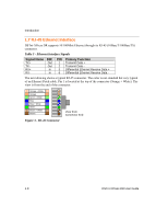
1.7 RJ-45 Ethernet Interface
DSTni-XPress DR supports 10/100Mbit Ethernet through its RJ-45 (10BaseT/100BaseTX)
connector.
Table 3 - Ethernet Interface Signals
Signal Name
DIR
PIN
Primary Function
TX+
Out
1
Transmit Data +
TX-
Out
2
Transmit Data -
RX+
In
3
Differential Ethernet Receive Data +
RX-
In
6
Differential Ethernet Receive Data -
The next drawing shows a typical RJ-45 connector. The color is not standard but very typical
of an Ethernet Patch cable. Pin 1 is located at the top of the connector (Orange + White). The
view is from the end of the connector.
Orange + White
Orange
Green + White
Blue
Blue + White
Green
Brown + White
Brown
View from
Connector End
Figure 3 - RJ-45 Connector
1-8
DSTni-XPress DR User Guide