Lantronix XPress-DR XPress-DR / XPress-DR-IAP - User Guide - Page 23
Serial Interface Connections, 8.1 9-Pin RS-232 to Serial RJ-45
 |
View all Lantronix XPress-DR manuals
Add to My Manuals
Save this manual to your list of manuals |
Page 23 highlights
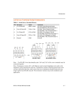
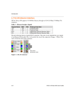
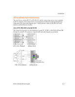
Introduction 1.8 Serial Interface Connections The serial device can be RS-232 or RS-485/422 and the connections can be screw terminals or RJ-45 connector. This section shows several practical methods for making the hardware connections. The following diagrams show typical interface cables for the RS-232 Serial interface and the Ethernet interface. 1.8.1 9-Pin RS-232 to Serial RJ-45 This connection assumes you are connecting a typical PC (COM1) to the DSTni-XPress DR through the serial RJ-45 connector. A pinout table and cable diagram are included. 4 DTR (Out) 6 DSR (In) 3 TXD (Out) 2 RXD (In) 5 Signal Ground 7 RTS (Out) 8 CTS (In) 1 No Connection 2 DTR (Out) 3 RXD (In) 4 TXD (Out) 5 Signal Ground 6 CTS (In) 7 RTS (Out) 8 No Connection DTE, 9-Pin, FEMALE SERIAL RJ-45 GND 5 DTR 9 CTS 8 RTS 7 DSR 6 4 3 TXD 2 RXD 1 DTE, 9-Pin, FEMALE 1 3 4 5 View from 8 Connector End SERIAL RJ-45 DSTni-XPress DR User Guide 1-9
-
 1
1 -
2
-
3
-
4
-
5
-
6
-
7
-
8
-
9
-
10
-
11
-
12
-
13
-
14
-
15
-
16
-
17
-
 18
18 -
 19
19 -
 20
20 -
 21
21 -
 22
22 -
 23
23 -
 24
24 -
 25
25 -
 26
26 -
 27
27 -
 28
28 -
29
-
30
-
31
-
32
-
33
-
34
-
35
-
36
-
37
-
38
-
39
-
40
-
41
-
42
-
43
-
44
-
45
-
46
-
47
-
48
-
49
-
50
-
51
-
52
-
53
-
54
-
55
-
56
-
57
-
58
-
59
-
60
-
61
-
62
-
63
-
64
-
65
-
66
-
67
-
68
-
69
-
70
-
71
-
72
-
73
-
74
-
75
-
76
-
77
-
78
-
79
-
80
-
81
-
82
-
83
-
84
-
85
-
86
-
87
-
88
-
89
-
90
-
91
-
92
-
93
-
94
-
95
-
96
-
97
-
98
-
99
-
100
-
101
-
102
-
103
-
104
-
105
-
106
-
107
-
108
-
109
-
110
-
111
-
112
-
113
-
114
-
115
-
116
-
117
-
118
-
119
-
120
-
121
-
122
-
123
-
124
-
125
-
126
-
127
-
128
-
129
-
130
-
131
-
132
-
133
-
134
-
135
-
136
-
137
-
138
-
139
-
140
-
141
-
142
-
143
-
144
-
145
-
146
-
147
-
148
-
149
 |
 |
