Lenovo S200 Hardware Maintenance Manual - Page 122
Replacing, power, switch/LED, assembly
 |
View all Lenovo S200 manuals
Add to My Manuals
Save this manual to your list of manuals |
Page 122 highlights
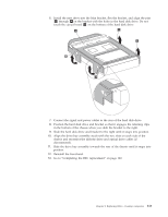
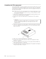
Replacing the power switch/LED assembly This procedure describes how to remove and replace the power switch/LED assembly. 1. Remove cover. See "Removing the cover" on page 85. 2. Remove the drive bay assembly. See "Accessing system board components and drives" on page 90. 3. Remove the hard disk drive. See "Replacing the hard disk drive" on page 112. 4. Disconnect the power switch/LED assembly cable from the system board. See the system board illustration for your machine type at "Locating parts on the system board" on page 87. 5. Remove the screw that secures the power switch/LED assembly to the chassis. 6. Note the power switch/LED assembly cable routing and remove the assembly from the chassis. 7. Route the cable for the new power switch/LED assembly through the hole in the chassis and to the system board. 8. Install the power switch/LED assembly into the chassis and secure the assembly with the screw. 9. Connect the power switch/LED cable to the system board. 10. Reinstall the hard disk drive. See "Replacing the hard disk drive" on page 112. 11. Align the drive bay assembly with the two slots and rails on the sides of the chassis slide the drive bay assembly towards the rear of the chassis until it snaps into position. 12. Reinstall the front bezel. 13. Go to "Completing the FRU replacement" on page 120. 116 Hardware Maintenance Manual
-
 1
1 -
2
-
3
-
4
-
5
-
6
-
7
-
8
-
9
-
10
-
11
-
12
-
13
-
14
-
15
-
16
-
17
-
18
-
19
-
20
-
21
-
22
-
23
-
24
-
25
-
26
-
27
-
28
-
29
-
30
-
31
-
32
-
33
-
34
-
35
-
36
-
37
-
38
-
39
-
40
-
41
-
42
-
43
-
44
-
45
-
46
-
47
-
48
-
49
-
50
-
51
-
52
-
53
-
54
-
55
-
56
-
57
-
58
-
59
-
60
-
61
-
62
-
63
-
64
-
65
-
66
-
67
-
68
-
69
-
70
-
71
-
72
-
73
-
74
-
75
-
76
-
77
-
78
-
79
-
80
-
81
-
82
-
83
-
84
-
85
-
86
-
87
-
88
-
89
-
90
-
91
-
92
-
93
-
94
-
95
-
96
-
97
-
98
-
99
-
100
-
101
-
102
-
103
-
104
-
105
-
106
-
107
-
108
-
109
-
110
-
111
-
112
-
113
-
114
-
115
-
116
-
 117
117 -
 118
118 -
 119
119 -
 120
120 -
 121
121 -
 122
122 -
 123
123 -
 124
124 -
 125
125 -
 126
126 -
 127
127 -
128
-
129
-
130
-
131
-
132
-
133
-
134
-
135
-
136
-
137
-
138
-
139
-
140
-
141
-
142
-
143
-
144
-
145
-
146
-
147
-
148
-
149
-
150
-
151
-
152
-
153
-
154
-
155
-
156
-
157
-
158
-
159
-
160
-
161
-
162
-
163
-
164
-
165
-
166
-
167
-
168
-
169
-
170
-
171
-
172
-
173
-
174
-
175
-
176
-
177
-
178
-
179
-
180
-
181
-
182
-
183
-
184
-
185
-
186
-
187
-
188
-
189
-
190
-
191
-
192
-
193
-
194
-
195
-
196
-
197
-
198
-
199
-
200
-
201
-
202
-
203
-
204
-
205
-
206
-
207
-
208
-
209
-
210
-
211
-
212
-
213
-
214
-
215
-
216
-
217
-
218
-
219
-
220
-
221
-
222
-
223
-
224
-
225
-
226
-
227
-
228
-
229
-
230
-
231
-
232
-
233
-
234
-
235
-
236
-
237
-
238
-
239
-
240
-
241
-
242
-
243
-
244
-
245
-
246
-
247
-
248
-
249
-
250
-
251
-
252
-
253
-
254
-
255
-
256
 |
 |
