Lenovo S200 Hardware Maintenance Manual - Page 140
connections
 |
View all Lenovo S200 manuals
Add to My Manuals
Save this manual to your list of manuals |
Page 140 highlights
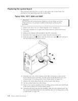
Types 7818, 7819, 9688, 9689, 9690, and 9691 Important The heat sink and microprocessor might be very hot. Make sure these components are cool enough to safely handle before continuing this procedure. Note: When replacing the system board you must also order a new retention module for the new system board. Make sure you have a retention module for the new system board before continuing with this procedure. 1. Remove the cover. See "Removing the cover" on page 123. 2. Place the computer on its right side to help make the system board more accessible. 3. Remove any adapter cards installed in the PCI connectors. 4. Disconnect the signal and power cables from the hard disk drive. 5. Press the release tab 1 down, slide the hard drive cage 2 back, and pivot the hard disk drive outward as shown. 6. Carefully take note of the location of all cable connections on the system board and disconnect all cables. See the system board illustration for your machine type at "Locating parts on the system board" on page 125. 7. Remove the screws that secure the system board to the chassis. 8. Lift the system board out of the chassis. 9. Remove the memory modules from the failing system board and install them in the same location on the new system board. 10. Disconnect the heat sink and fan assembly cable from the system board. See the system board illustration for your machine type at "Locating parts on the system board" on page 125. 11. Remove the four screws 1 securing the heat sink and fan assembly to the system board. 134 Hardware Maintenance Manual
-
 1
1 -
2
-
3
-
4
-
5
-
6
-
7
-
8
-
9
-
10
-
11
-
12
-
13
-
14
-
15
-
16
-
17
-
18
-
19
-
20
-
21
-
22
-
23
-
24
-
25
-
26
-
27
-
28
-
29
-
30
-
31
-
32
-
33
-
34
-
35
-
36
-
37
-
38
-
39
-
40
-
41
-
42
-
43
-
44
-
45
-
46
-
47
-
48
-
49
-
50
-
51
-
52
-
53
-
54
-
55
-
56
-
57
-
58
-
59
-
60
-
61
-
62
-
63
-
64
-
65
-
66
-
67
-
68
-
69
-
70
-
71
-
72
-
73
-
74
-
75
-
76
-
77
-
78
-
79
-
80
-
81
-
82
-
83
-
84
-
85
-
86
-
87
-
88
-
89
-
90
-
91
-
92
-
93
-
94
-
95
-
96
-
97
-
98
-
99
-
100
-
101
-
102
-
103
-
104
-
105
-
106
-
107
-
108
-
109
-
110
-
111
-
112
-
113
-
114
-
115
-
116
-
117
-
118
-
119
-
120
-
121
-
122
-
123
-
124
-
125
-
126
-
127
-
128
-
129
-
130
-
131
-
132
-
133
-
134
-
 135
135 -
 136
136 -
 137
137 -
 138
138 -
 139
139 -
 140
140 -
 141
141 -
 142
142 -
 143
143 -
 144
144 -
 145
145 -
146
-
147
-
148
-
149
-
150
-
151
-
152
-
153
-
154
-
155
-
156
-
157
-
158
-
159
-
160
-
161
-
162
-
163
-
164
-
165
-
166
-
167
-
168
-
169
-
170
-
171
-
172
-
173
-
174
-
175
-
176
-
177
-
178
-
179
-
180
-
181
-
182
-
183
-
184
-
185
-
186
-
187
-
188
-
189
-
190
-
191
-
192
-
193
-
194
-
195
-
196
-
197
-
198
-
199
-
200
-
201
-
202
-
203
-
204
-
205
-
206
-
207
-
208
-
209
-
210
-
211
-
212
-
213
-
214
-
215
-
216
-
217
-
218
-
219
-
220
-
221
-
222
-
223
-
224
-
225
-
226
-
227
-
228
-
229
-
230
-
231
-
232
-
233
-
234
-
235
-
236
-
237
-
238
-
239
-
240
-
241
-
242
-
243
-
244
-
245
-
246
-
247
-
248
-
249
-
250
-
251
-
252
-
253
-
254
-
255
-
256
 |
 |
