Lenovo S200 Hardware Maintenance Manual - Page 151
Install
 |
View all Lenovo S200 manuals
Add to My Manuals
Save this manual to your list of manuals |
Page 151 highlights
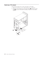
11. Lower the microprocessor straight down into the system board socket of the system board. 12. To secure the microprocessor in the socket, close the microprocessor retainer and lock it into position with the small handle. 13. Install the heat sink and fan assembly on the system board. 14. Connect the heat sink and fan assembly cable to the system board. See the system board illustration for your machine type at "Locating parts on the system board" on page 125. 15. Go to "Completing the FRU replacement" on page 161. Chapter 9. Replacing FRUs - Tower Computers 145
-
 1
1 -
2
-
3
-
4
-
5
-
6
-
7
-
8
-
9
-
10
-
11
-
12
-
13
-
14
-
15
-
16
-
17
-
18
-
19
-
20
-
21
-
22
-
23
-
24
-
25
-
26
-
27
-
28
-
29
-
30
-
31
-
32
-
33
-
34
-
35
-
36
-
37
-
38
-
39
-
40
-
41
-
42
-
43
-
44
-
45
-
46
-
47
-
48
-
49
-
50
-
51
-
52
-
53
-
54
-
55
-
56
-
57
-
58
-
59
-
60
-
61
-
62
-
63
-
64
-
65
-
66
-
67
-
68
-
69
-
70
-
71
-
72
-
73
-
74
-
75
-
76
-
77
-
78
-
79
-
80
-
81
-
82
-
83
-
84
-
85
-
86
-
87
-
88
-
89
-
90
-
91
-
92
-
93
-
94
-
95
-
96
-
97
-
98
-
99
-
100
-
101
-
102
-
103
-
104
-
105
-
106
-
107
-
108
-
109
-
110
-
111
-
112
-
113
-
114
-
115
-
116
-
117
-
118
-
119
-
120
-
121
-
122
-
123
-
124
-
125
-
126
-
127
-
128
-
129
-
130
-
131
-
132
-
133
-
134
-
135
-
136
-
137
-
138
-
139
-
140
-
141
-
142
-
143
-
144
-
145
-
 146
146 -
 147
147 -
 148
148 -
 149
149 -
 150
150 -
 151
151 -
 152
152 -
 153
153 -
 154
154 -
 155
155 -
 156
156 -
157
-
158
-
159
-
160
-
161
-
162
-
163
-
164
-
165
-
166
-
167
-
168
-
169
-
170
-
171
-
172
-
173
-
174
-
175
-
176
-
177
-
178
-
179
-
180
-
181
-
182
-
183
-
184
-
185
-
186
-
187
-
188
-
189
-
190
-
191
-
192
-
193
-
194
-
195
-
196
-
197
-
198
-
199
-
200
-
201
-
202
-
203
-
204
-
205
-
206
-
207
-
208
-
209
-
210
-
211
-
212
-
213
-
214
-
215
-
216
-
217
-
218
-
219
-
220
-
221
-
222
-
223
-
224
-
225
-
226
-
227
-
228
-
229
-
230
-
231
-
232
-
233
-
234
-
235
-
236
-
237
-
238
-
239
-
240
-
241
-
242
-
243
-
244
-
245
-
246
-
247
-
248
-
249
-
250
-
251
-
252
-
253
-
254
-
255
-
256
 |
 |

11.
Lower
the
microprocessor
straight
down
into
the
system
board
socket
of
the
system
board.
12.
To
secure
the
microprocessor
in
the
socket,
close
the
microprocessor
retainer
and
lock
it
into
position
with
the
small
handle.
13.
Install
the
heat
sink
and
fan
assembly
on
the
system
board.
14.
Connect
the
heat
sink
and
fan
assembly
cable
to
the
system
board.
See
the
system
board
illustration
for
your
machine
type
at
“Locating
parts
on
the
system
board”
on
page
125.
15.
Go
to
“Completing
the
FRU
replacement”
on
page
161.
Chapter
9.
Replacing
FRUs
-
Tower
Computers
145