Lenovo S200 Hardware Maintenance Manual - Page 135
Lenovo S200 Manual
 |
View all Lenovo S200 manuals
Add to My Manuals
Save this manual to your list of manuals |
Page 135 highlights
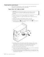
Replacing the power supply This procedure describes how to remove and replace the power supply. 1. Remove the computer cover. See "Removing the cover" on page 123. Note: For this procedure, it helps to lay the computer on its side. 2. Disconnect the power supply cables from the system board and from all drives. 3. Remove the four screws that secure the power supply at the rear of the chassis. 4. Lift the power supply out of the chassis. 5. If the power supply has a voltage-selection switch, ensure that it is set to match the voltage available at the electrical outlet. v If the voltage supply range in your local country or region is 100-127 V ac, set the switch to 115 V. v If the voltage supply range in your local country or region is 200-240 V ac, set the switch to 230 V. 6. Install the new power supply into the chassis so that the screw holes in the power supply align with those in the chassis. 7. Install the four screws to secure the power supply. Note: Use only the screws provided by Lenovo. 8. Reconnect the power supply connectors to the system board. See "Locating parts on the system board" on page 125. 9. Reconnect a power supply connector to each of the drives. 10. Go to "Completing the FRU replacement" on page 161. Chapter 9. Replacing FRUs - Tower Computers 129
-
 1
1 -
2
-
3
-
4
-
5
-
6
-
7
-
8
-
9
-
10
-
11
-
12
-
13
-
14
-
15
-
16
-
17
-
18
-
19
-
20
-
21
-
22
-
23
-
24
-
25
-
26
-
27
-
28
-
29
-
30
-
31
-
32
-
33
-
34
-
35
-
36
-
37
-
38
-
39
-
40
-
41
-
42
-
43
-
44
-
45
-
46
-
47
-
48
-
49
-
50
-
51
-
52
-
53
-
54
-
55
-
56
-
57
-
58
-
59
-
60
-
61
-
62
-
63
-
64
-
65
-
66
-
67
-
68
-
69
-
70
-
71
-
72
-
73
-
74
-
75
-
76
-
77
-
78
-
79
-
80
-
81
-
82
-
83
-
84
-
85
-
86
-
87
-
88
-
89
-
90
-
91
-
92
-
93
-
94
-
95
-
96
-
97
-
98
-
99
-
100
-
101
-
102
-
103
-
104
-
105
-
106
-
107
-
108
-
109
-
110
-
111
-
112
-
113
-
114
-
115
-
116
-
117
-
118
-
119
-
120
-
121
-
122
-
123
-
124
-
125
-
126
-
127
-
128
-
129
-
 130
130 -
 131
131 -
 132
132 -
 133
133 -
 134
134 -
 135
135 -
 136
136 -
 137
137 -
 138
138 -
 139
139 -
 140
140 -
141
-
142
-
143
-
144
-
145
-
146
-
147
-
148
-
149
-
150
-
151
-
152
-
153
-
154
-
155
-
156
-
157
-
158
-
159
-
160
-
161
-
162
-
163
-
164
-
165
-
166
-
167
-
168
-
169
-
170
-
171
-
172
-
173
-
174
-
175
-
176
-
177
-
178
-
179
-
180
-
181
-
182
-
183
-
184
-
185
-
186
-
187
-
188
-
189
-
190
-
191
-
192
-
193
-
194
-
195
-
196
-
197
-
198
-
199
-
200
-
201
-
202
-
203
-
204
-
205
-
206
-
207
-
208
-
209
-
210
-
211
-
212
-
213
-
214
-
215
-
216
-
217
-
218
-
219
-
220
-
221
-
222
-
223
-
224
-
225
-
226
-
227
-
228
-
229
-
230
-
231
-
232
-
233
-
234
-
235
-
236
-
237
-
238
-
239
-
240
-
241
-
242
-
243
-
244
-
245
-
246
-
247
-
248
-
249
-
250
-
251
-
252
-
253
-
254
-
255
-
256
 |
 |
