Lenovo S200 Hardware Maintenance Manual - Page 152
Installing, memory
 |
View all Lenovo S200 manuals
Add to My Manuals
Save this manual to your list of manuals |
Page 152 highlights
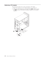
Replacing a memory module This procedure describes how to remove and replace a memory module. Installing memory This computer either has two or four connectors for installing double data rate 2 dual inline memory modules (DDR2 DIMMs). System boards with two connectors can accommodate a maximum of 2.0 GB of system memory. System boards with four connectors can accommodate a maximum of 4.0 GB of system memory. When installing memory modules, the following rules apply: v If you are replacing a memory module on a system board with four memory connectors, at least one memory module must be installed in the first memory channel (in either memory connector 1 or memory connector 2). See "Locating parts on the system board" on page 125for more information. v Use 1.8 V, 240-pin, double data rate 2 synchronous dynamic random access memory (DDR2 SDRAM). v Use 256 MB, 512 MB, or 1 GB memory modules in any combination. Note: Only DDR2 SDRAM DIMMs can be used. 1. Remove the computer cover. See "Removing the cover" on page 123. Note: For this procedure, it helps to lay the computer on its side. 2. Locate the memory module connectors. See "Locating parts on the system board" on page 125. 3. Remove the memory module being replaced by opening the retaining clips as shown. 4. Position the new memory module over the memory connector. Make sure the notch 1 on the memory aligns correctly with the connector key 2 on the system board. Push the memory module straight down into the connector until 146 Hardware Maintenance Manual
-
 1
1 -
2
-
3
-
4
-
5
-
6
-
7
-
8
-
9
-
10
-
11
-
12
-
13
-
14
-
15
-
16
-
17
-
18
-
19
-
20
-
21
-
22
-
23
-
24
-
25
-
26
-
27
-
28
-
29
-
30
-
31
-
32
-
33
-
34
-
35
-
36
-
37
-
38
-
39
-
40
-
41
-
42
-
43
-
44
-
45
-
46
-
47
-
48
-
49
-
50
-
51
-
52
-
53
-
54
-
55
-
56
-
57
-
58
-
59
-
60
-
61
-
62
-
63
-
64
-
65
-
66
-
67
-
68
-
69
-
70
-
71
-
72
-
73
-
74
-
75
-
76
-
77
-
78
-
79
-
80
-
81
-
82
-
83
-
84
-
85
-
86
-
87
-
88
-
89
-
90
-
91
-
92
-
93
-
94
-
95
-
96
-
97
-
98
-
99
-
100
-
101
-
102
-
103
-
104
-
105
-
106
-
107
-
108
-
109
-
110
-
111
-
112
-
113
-
114
-
115
-
116
-
117
-
118
-
119
-
120
-
121
-
122
-
123
-
124
-
125
-
126
-
127
-
128
-
129
-
130
-
131
-
132
-
133
-
134
-
135
-
136
-
137
-
138
-
139
-
140
-
141
-
142
-
143
-
144
-
145
-
146
-
 147
147 -
 148
148 -
 149
149 -
 150
150 -
 151
151 -
 152
152 -
 153
153 -
 154
154 -
 155
155 -
 156
156 -
 157
157 -
158
-
159
-
160
-
161
-
162
-
163
-
164
-
165
-
166
-
167
-
168
-
169
-
170
-
171
-
172
-
173
-
174
-
175
-
176
-
177
-
178
-
179
-
180
-
181
-
182
-
183
-
184
-
185
-
186
-
187
-
188
-
189
-
190
-
191
-
192
-
193
-
194
-
195
-
196
-
197
-
198
-
199
-
200
-
201
-
202
-
203
-
204
-
205
-
206
-
207
-
208
-
209
-
210
-
211
-
212
-
213
-
214
-
215
-
216
-
217
-
218
-
219
-
220
-
221
-
222
-
223
-
224
-
225
-
226
-
227
-
228
-
229
-
230
-
231
-
232
-
233
-
234
-
235
-
236
-
237
-
238
-
239
-
240
-
241
-
242
-
243
-
244
-
245
-
246
-
247
-
248
-
249
-
250
-
251
-
252
-
253
-
254
-
255
-
256
 |
 |
