Lenovo ThinkPad T430s (English) User Guide - Page 99
If the new PCI Express Mini Card has three connectors, be sure to attach the gray cable to
 |
View all Lenovo ThinkPad T430s manuals
Add to My Manuals
Save this manual to your list of manuals |
Page 99 highlights
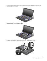
9. Pivot the card until you can snap it into place by pressing the upper side of the connectors 1 , and secure the card with the screw 2 . 10. Connect the cables to the new PCI Express Mini Card. Be sure to attach the gray cable to the connector marked "MAIN" or "M" on the card, and the black cable to the connector marked "AUX" or "A". Note: If the new PCI Express Mini Card has three connectors, be sure to attach the gray cable to the connector marked "TR1" on the card, and the black cable to the connector marked "TR2". If you attach either cable to the center connector, the connection speed will be lower. 11. Reinstall the memory slot cover and tighten the screws. Chapter 6. Replacing devices 81
-
 1
1 -
2
-
3
-
4
-
5
-
6
-
7
-
8
-
9
-
10
-
11
-
12
-
13
-
14
-
15
-
16
-
17
-
18
-
19
-
20
-
21
-
22
-
23
-
24
-
25
-
26
-
27
-
28
-
29
-
30
-
31
-
32
-
33
-
34
-
35
-
36
-
37
-
38
-
39
-
40
-
41
-
42
-
43
-
44
-
45
-
46
-
47
-
48
-
49
-
50
-
51
-
52
-
53
-
54
-
55
-
56
-
57
-
58
-
59
-
60
-
61
-
62
-
63
-
64
-
65
-
66
-
67
-
68
-
69
-
70
-
71
-
72
-
73
-
74
-
75
-
76
-
77
-
78
-
79
-
80
-
81
-
82
-
83
-
84
-
85
-
86
-
87
-
88
-
89
-
90
-
91
-
92
-
93
-
 94
94 -
 95
95 -
 96
96 -
 97
97 -
 98
98 -
 99
99 -
 100
100 -
 101
101 -
 102
102 -
 103
103 -
 104
104 -
105
-
106
-
107
-
108
-
109
-
110
-
111
-
112
-
113
-
114
-
115
-
116
-
117
-
118
-
119
-
120
-
121
-
122
-
123
-
124
-
125
-
126
-
127
-
128
-
129
-
130
-
131
-
132
-
133
-
134
-
135
-
136
-
137
-
138
-
139
-
140
-
141
-
142
-
143
-
144
-
145
-
146
-
147
-
148
-
149
-
150
-
151
-
152
-
153
-
154
-
155
-
156
-
157
-
158
-
159
-
160
-
161
-
162
-
163
-
164
-
165
-
166
-
167
-
168
-
169
-
170
-
171
-
172
-
173
-
174
-
175
-
176
-
177
-
178
-
179
-
180
-
181
-
182
-
183
-
184
-
185
-
186
-
187
-
188
-
189
-
190
-
191
-
192
 |
 |

9. Pivot the card until you can snap it into place by pressing the upper side of the connectors
1
, and
secure the card with the screw
2
.
10. Connect the cables to the new PCI Express Mini Card. Be sure to attach the gray cable to the connector
marked “MAIN” or “M” on the card, and the black cable to the connector marked “AUX” or “A”.
Note:
If the new PCI Express Mini Card has three connectors, be sure to attach the gray cable to the
connector marked “TR1” on the card, and the black cable to the connector marked “TR2”. If you attach
either cable to the center connector, the connection speed will be lower.
11. Reinstall the memory slot cover and tighten the screws.
Chapter 6
.
Replacing devices
81