Lenovo ThinkStation C20 Hardware Maintenance Manual - ThinkStation C20/C20x - Page 101
Replacing the system board
 |
View all Lenovo ThinkStation C20 manuals
Add to My Manuals
Save this manual to your list of manuals |
Page 101 highlights
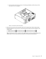
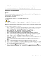
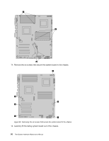
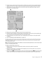
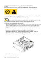
13. Reinstall the PCI card holder into the chassis. See "Removing and reinstalling the PCI card holder" on page 76. 14. Reinstall the front bezel. See "Removing and reinstalling the front bezel" on page 75. 15. To complete the replacement, go to "Completing the parts replacement" on page 110. Replacing the system board Attention Do not open your computer or attempt any repair before reading and understanding the "Important safety information" in the ThinkStation Safety and Warranty Guide that came with your computer. To obtain a copy of the ThinkStation Safety and Warranty Guide, go to: http://www.lenovo.com/support This section provides instructions on how to replace the system board. CAUTION: The heat sink and microprocessor might be very hot. Turn off the computer and wait three to five minutes to let the computer cool before removing the computer cover. Note: Before replacing the system board, make sure you have a retention module for the new system board. To replace the system board, do the following: 1. Remove all media from the drives and turn off all attached devices and the computer. Then, disconnect all power cords from electrical outlets and disconnect all cables that are connected to the computer. 2. Remove the computer cover. See "Removing the computer cover" on page 74. 3. Remove the front bezel. See "Removing and reinstalling the front bezel" on page 75. 4. Place the computer on its side to gain easier access to the system board. 5. Remove the PCI card holder. See "Removing and reinstalling the PCI card holder" on page 76. 6. Remove the optical drive and the optical drive bracket. See "Replacing the optical drive" on page 88. 7. Remove all memory modules and PCI cards that are currently installed. See "Installing or replacing a memory module" on page 78 and "Installing or replacing a PCI card" on page 82. 8. Remove the heat sink and fan assembly from the failing system board. See "Replacing the heat sink and fan assembly" on page 90. 9. Remove the microprocessor from the failing system board. See "Replacing the microprocessor" on page 93. 10. Remove the battery from the failing system board. See "Replacing the battery" on page 98. 11. Remove the front fan assembly from the computer. See "Replacing the front fan assembly" on page 104. 12. Note the location of all cable connections on the system board and disconnect all cables. See "Locating parts and connectors on the system board" on page 71. 13. Remove the three screws 1 that secure the memory chiller frame. Remove the three screws 2 that secure the other memory chiller frame. Then, remove the two screws 3 that secure the black cable clip. Chapter 9. Replacing FRUs 95
-
 1
1 -
2
-
3
-
4
-
5
-
6
-
7
-
8
-
9
-
10
-
11
-
12
-
13
-
14
-
15
-
16
-
17
-
18
-
19
-
20
-
21
-
22
-
23
-
24
-
25
-
26
-
27
-
28
-
29
-
30
-
31
-
32
-
33
-
34
-
35
-
36
-
37
-
38
-
39
-
40
-
41
-
42
-
43
-
44
-
45
-
46
-
47
-
48
-
49
-
50
-
51
-
52
-
53
-
54
-
55
-
56
-
57
-
58
-
59
-
60
-
61
-
62
-
63
-
64
-
65
-
66
-
67
-
68
-
69
-
70
-
71
-
72
-
73
-
74
-
75
-
76
-
77
-
78
-
79
-
80
-
81
-
82
-
83
-
84
-
85
-
86
-
87
-
88
-
89
-
90
-
91
-
92
-
93
-
94
-
95
-
 96
96 -
 97
97 -
 98
98 -
 99
99 -
 100
100 -
 101
101 -
 102
102 -
 103
103 -
 104
104 -
 105
105 -
 106
106 -
107
-
108
-
109
-
110
-
111
-
112
-
113
-
114
-
115
-
116
-
117
-
118
-
119
-
120
-
121
-
122
-
123
-
124
-
125
-
126
-
127
-
128
-
129
-
130
-
131
-
132
-
133
-
134
-
135
-
136
-
137
-
138
-
139
-
140
-
141
-
142
-
143
-
144
-
145
-
146
-
147
-
148
-
149
-
150
-
151
-
152
-
153
-
154
-
155
-
156
-
157
-
158
-
159
-
160
-
161
-
162
-
163
-
164
-
165
-
166
-
167
-
168
-
169
-
170
-
171
-
172
-
173
-
174
-
175
-
176
-
177
-
178
-
179
-
180
-
181
-
182
-
183
-
184
-
185
-
186
-
187
-
188
-
189
-
190
-
191
-
192
-
193
-
194
-
195
-
196
-
197
-
198
-
199
-
200
-
201
-
202
-
203
-
204
-
205
-
206
-
207
-
208
-
209
-
210
-
211
-
212
-
213
-
214
-
215
-
216
-
217
-
218
-
219
-
220
-
221
-
222
-
223
-
224
-
225
-
226
-
227
-
228
-
229
-
230
-
231
-
232
-
233
-
234
-
235
-
236
-
237
-
238
-
239
-
240
-
241
-
242
-
243
-
244
-
245
-
246
 |
 |