Lenovo ThinkStation C20 Hardware Maintenance Manual - ThinkStation C20/C20x - Page 88
Installing or replacing a PCI card
 |
View all Lenovo ThinkStation C20 manuals
Add to My Manuals
Save this manual to your list of manuals |
Page 88 highlights
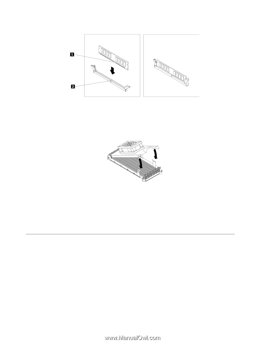
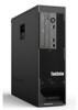
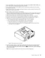
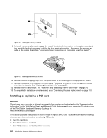
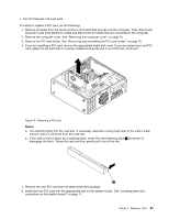
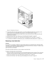
Figure 14. Installing a memory module 9. To install the memory fan duct, engage the rear of the duct with the retainer on the system board and then pivot the fan duct downward until the fan duct snaps into position. Reconnect the memory fan cable to the system board. See "Locating parts and connectors on the system board" on page 71. Figure 15. Installing the memory fan duct 10. Reinstall the blue shipping clip if your computer needs to be repackaged and shipped in the future. 11. Reinstall the optical drive bracket into the chassis if you have removed it. Then, reinstall the optical drive into the chassis. See "Replacing the optical drive" on page 88. 12. Reinstall the PCI card holder. See "Removing and reinstalling the PCI card holder" on page 76. 13. To complete the installation or replacement, go to "Completing the parts replacement" on page 110. Installing or replacing a PCI card Attention Do not open your computer or attempt any repair before reading and understanding the "Important safety information" in the ThinkStation Safety and Warranty Guide that came with your computer. To obtain a copy of the ThinkStation Safety and Warranty Guide, go to: http://www.lenovo.com/support This section provides instructions on how to install or replace a PCI card. Your computer has the following six expansion slots for installing or replacing PCI cards: • Two PCI card slots • One PCI Express x1 card slot • One PCI Express x4 card slot (x16 mechanical) 82 ThinkStation Hardware Maintenance Manual
-
 1
1 -
2
-
3
-
4
-
5
-
6
-
7
-
8
-
9
-
10
-
11
-
12
-
13
-
14
-
15
-
16
-
17
-
18
-
19
-
20
-
21
-
22
-
23
-
24
-
25
-
26
-
27
-
28
-
29
-
30
-
31
-
32
-
33
-
34
-
35
-
36
-
37
-
38
-
39
-
40
-
41
-
42
-
43
-
44
-
45
-
46
-
47
-
48
-
49
-
50
-
51
-
52
-
53
-
54
-
55
-
56
-
57
-
58
-
59
-
60
-
61
-
62
-
63
-
64
-
65
-
66
-
67
-
68
-
69
-
70
-
71
-
72
-
73
-
74
-
75
-
76
-
77
-
78
-
79
-
80
-
81
-
82
-
 83
83 -
 84
84 -
 85
85 -
 86
86 -
 87
87 -
 88
88 -
 89
89 -
 90
90 -
 91
91 -
 92
92 -
 93
93 -
94
-
95
-
96
-
97
-
98
-
99
-
100
-
101
-
102
-
103
-
104
-
105
-
106
-
107
-
108
-
109
-
110
-
111
-
112
-
113
-
114
-
115
-
116
-
117
-
118
-
119
-
120
-
121
-
122
-
123
-
124
-
125
-
126
-
127
-
128
-
129
-
130
-
131
-
132
-
133
-
134
-
135
-
136
-
137
-
138
-
139
-
140
-
141
-
142
-
143
-
144
-
145
-
146
-
147
-
148
-
149
-
150
-
151
-
152
-
153
-
154
-
155
-
156
-
157
-
158
-
159
-
160
-
161
-
162
-
163
-
164
-
165
-
166
-
167
-
168
-
169
-
170
-
171
-
172
-
173
-
174
-
175
-
176
-
177
-
178
-
179
-
180
-
181
-
182
-
183
-
184
-
185
-
186
-
187
-
188
-
189
-
190
-
191
-
192
-
193
-
194
-
195
-
196
-
197
-
198
-
199
-
200
-
201
-
202
-
203
-
204
-
205
-
206
-
207
-
208
-
209
-
210
-
211
-
212
-
213
-
214
-
215
-
216
-
217
-
218
-
219
-
220
-
221
-
222
-
223
-
224
-
225
-
226
-
227
-
228
-
229
-
230
-
231
-
232
-
233
-
234
-
235
-
236
-
237
-
238
-
239
-
240
-
241
-
242
-
243
-
244
-
245
-
246
 |
 |