Lenovo ThinkStation C20 Hardware Maintenance Manual - ThinkStation C20/C20x - Page 103
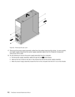
Release the lever securing the microprocessor retainer and open the retainer to access
 |
View all Lenovo ThinkStation C20 manuals
Add to My Manuals
Save this manual to your list of manuals |
Page 103 highlights
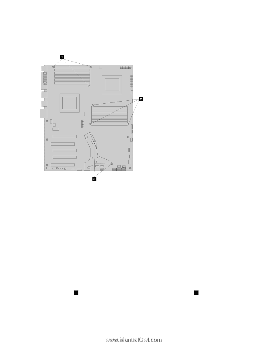
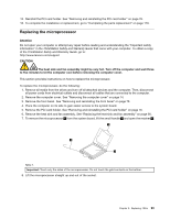
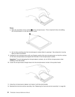
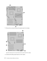
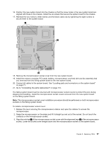
16. Position the new system board into the chassis so that the screw holes in the new system board are aligned with those in the chassis. Install the six screws that secure the system board to the chassis. 17. Reinstall the two memory chiller frames and the black cable clip by tightening the eight screws to secure them to the system board. 18. Remove the microprocessor socket cover from the new system board. 19. Install the memory modules, PCI cards, battery, microprocessor, and heat sink and fan assembly that you removed from the failing system board to the new system board. 20. Connect all cables to the system board. See "Locating parts and connectors on the system board" on page 71. 21. Go to "Completing the parts replacement" on page 110. The failing system board must be returned with microprocessor socket covers to protect the pins during shipping and handling. Install the microprocessor socket covers removed from the new system board on the failing system board. Note: The microprocessor socket cover installation procedure should be performed on both microprocessor sockets on the failing system board. To install a microprocessor socket cover: 1. Release the lever securing the microprocessor retainer and open the retainer to access the microprocessor. 2. Grasp the microprocessor on the sides and lift it straight up and out of the socket. Do not touch the contacts on the microprocessor socket. 3. Align the notches 1 of the microprocessor socket cover with the alignment keys 2 of the microprocessor socket. Lower the socket cover straight down into the microprocessor socket on the system board. Chapter 9. Replacing FRUs 97
-
 1
1 -
2
-
3
-
4
-
5
-
6
-
7
-
8
-
9
-
10
-
11
-
12
-
13
-
14
-
15
-
16
-
17
-
18
-
19
-
20
-
21
-
22
-
23
-
24
-
25
-
26
-
27
-
28
-
29
-
30
-
31
-
32
-
33
-
34
-
35
-
36
-
37
-
38
-
39
-
40
-
41
-
42
-
43
-
44
-
45
-
46
-
47
-
48
-
49
-
50
-
51
-
52
-
53
-
54
-
55
-
56
-
57
-
58
-
59
-
60
-
61
-
62
-
63
-
64
-
65
-
66
-
67
-
68
-
69
-
70
-
71
-
72
-
73
-
74
-
75
-
76
-
77
-
78
-
79
-
80
-
81
-
82
-
83
-
84
-
85
-
86
-
87
-
88
-
89
-
90
-
91
-
92
-
93
-
94
-
95
-
96
-
97
-
 98
98 -
 99
99 -
 100
100 -
 101
101 -
 102
102 -
 103
103 -
 104
104 -
 105
105 -
 106
106 -
 107
107 -
 108
108 -
109
-
110
-
111
-
112
-
113
-
114
-
115
-
116
-
117
-
118
-
119
-
120
-
121
-
122
-
123
-
124
-
125
-
126
-
127
-
128
-
129
-
130
-
131
-
132
-
133
-
134
-
135
-
136
-
137
-
138
-
139
-
140
-
141
-
142
-
143
-
144
-
145
-
146
-
147
-
148
-
149
-
150
-
151
-
152
-
153
-
154
-
155
-
156
-
157
-
158
-
159
-
160
-
161
-
162
-
163
-
164
-
165
-
166
-
167
-
168
-
169
-
170
-
171
-
172
-
173
-
174
-
175
-
176
-
177
-
178
-
179
-
180
-
181
-
182
-
183
-
184
-
185
-
186
-
187
-
188
-
189
-
190
-
191
-
192
-
193
-
194
-
195
-
196
-
197
-
198
-
199
-
200
-
201
-
202
-
203
-
204
-
205
-
206
-
207
-
208
-
209
-
210
-
211
-
212
-
213
-
214
-
215
-
216
-
217
-
218
-
219
-
220
-
221
-
222
-
223
-
224
-
225
-
226
-
227
-
228
-
229
-
230
-
231
-
232
-
233
-
234
-
235
-
236
-
237
-
238
-
239
-
240
-
241
-
242
-
243
-
244
-
245
-
246
 |
 |