Lenovo ThinkStation C20 Hardware Maintenance Manual - ThinkStation C20/C20x - Page 108
Interconnect PCI cards., in the chassis.
 |
View all Lenovo ThinkStation C20 manuals
Add to My Manuals
Save this manual to your list of manuals |
Page 108 highlights
Figure 32. Removing the side cover 11. Disconnect the power supply assembly cables from the system board and the drives. In some models, you might need to disconnect the power supply assembly cables from the Peripheral Component Interconnect (PCI) cards. 12. Do the following to remove the power supply assembly from the computer: a. Pull the power supply assembly cables through the hole 1 in the chassis. b. Remove the four screws at the rear of the chassis that secure the power supply assembly. c. Slide the power supply assembly toward the front of the computer and then lift it out of the chassis. 102 ThinkStation Hardware Maintenance Manual
-
 1
1 -
2
-
3
-
4
-
5
-
6
-
7
-
8
-
9
-
10
-
11
-
12
-
13
-
14
-
15
-
16
-
17
-
18
-
19
-
20
-
21
-
22
-
23
-
24
-
25
-
26
-
27
-
28
-
29
-
30
-
31
-
32
-
33
-
34
-
35
-
36
-
37
-
38
-
39
-
40
-
41
-
42
-
43
-
44
-
45
-
46
-
47
-
48
-
49
-
50
-
51
-
52
-
53
-
54
-
55
-
56
-
57
-
58
-
59
-
60
-
61
-
62
-
63
-
64
-
65
-
66
-
67
-
68
-
69
-
70
-
71
-
72
-
73
-
74
-
75
-
76
-
77
-
78
-
79
-
80
-
81
-
82
-
83
-
84
-
85
-
86
-
87
-
88
-
89
-
90
-
91
-
92
-
93
-
94
-
95
-
96
-
97
-
98
-
99
-
100
-
101
-
102
-
 103
103 -
 104
104 -
 105
105 -
 106
106 -
 107
107 -
 108
108 -
 109
109 -
 110
110 -
 111
111 -
 112
112 -
 113
113 -
114
-
115
-
116
-
117
-
118
-
119
-
120
-
121
-
122
-
123
-
124
-
125
-
126
-
127
-
128
-
129
-
130
-
131
-
132
-
133
-
134
-
135
-
136
-
137
-
138
-
139
-
140
-
141
-
142
-
143
-
144
-
145
-
146
-
147
-
148
-
149
-
150
-
151
-
152
-
153
-
154
-
155
-
156
-
157
-
158
-
159
-
160
-
161
-
162
-
163
-
164
-
165
-
166
-
167
-
168
-
169
-
170
-
171
-
172
-
173
-
174
-
175
-
176
-
177
-
178
-
179
-
180
-
181
-
182
-
183
-
184
-
185
-
186
-
187
-
188
-
189
-
190
-
191
-
192
-
193
-
194
-
195
-
196
-
197
-
198
-
199
-
200
-
201
-
202
-
203
-
204
-
205
-
206
-
207
-
208
-
209
-
210
-
211
-
212
-
213
-
214
-
215
-
216
-
217
-
218
-
219
-
220
-
221
-
222
-
223
-
224
-
225
-
226
-
227
-
228
-
229
-
230
-
231
-
232
-
233
-
234
-
235
-
236
-
237
-
238
-
239
-
240
-
241
-
242
-
243
-
244
-
245
-
246
 |
 |
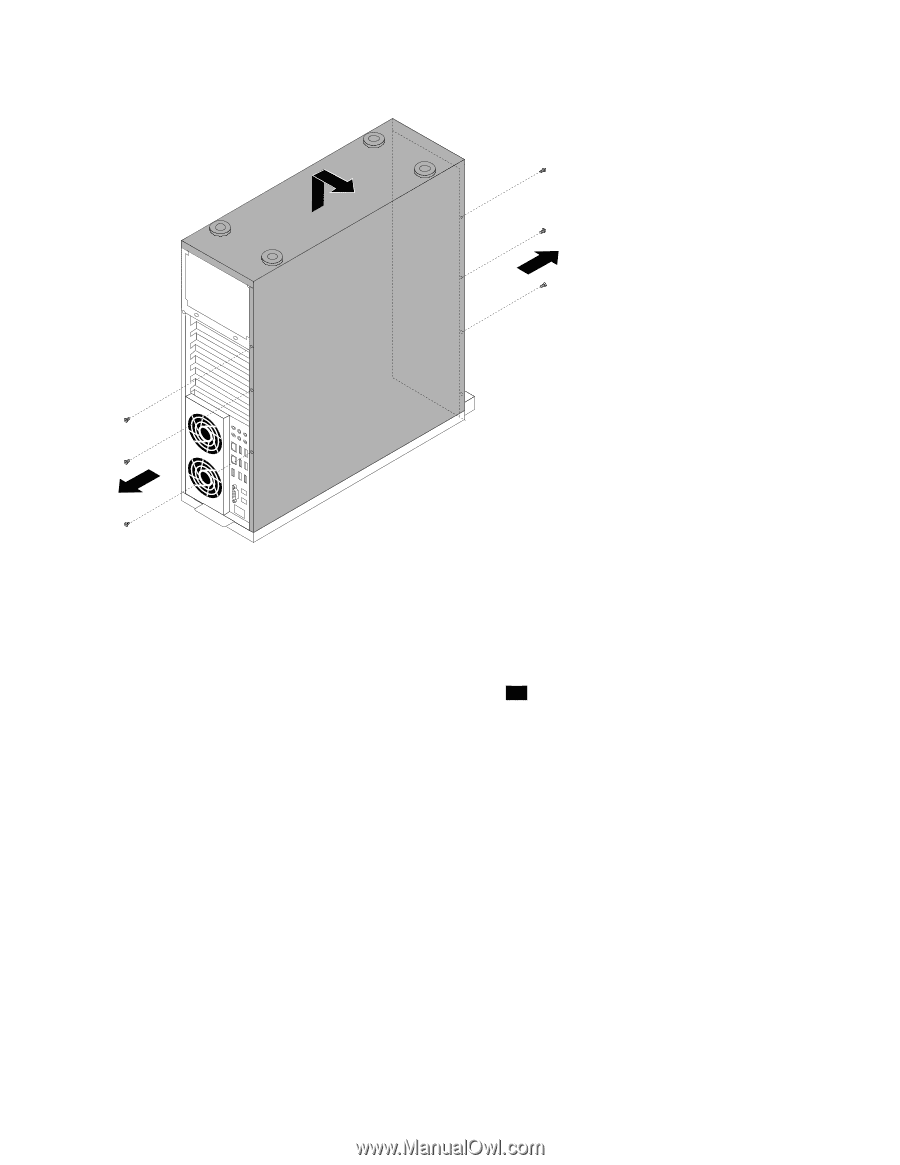
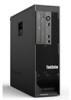
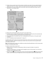
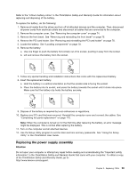
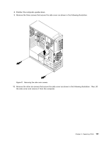
Figure 32. Removing the side cover
11. Disconnect the power supply assembly cables from the system board and the drives. In some models,
you might need to disconnect the power supply assembly cables from the Peripheral Component
Interconnect (PCI) cards.
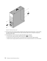
12. Do the following to remove the power supply assembly from the computer:
a.
Pull the power supply assembly cables through the hole
1
in the chassis.
b. Remove the four screws at the rear of the chassis that secure the power supply assembly.
c.
Slide the power supply assembly toward the front of the computer and then lift it out of the chassis.
102
ThinkStation Hardware Maintenance Manual