Lenovo ThinkStation C20 Hardware Maintenance Manual - ThinkStation C20/C20x - Page 109
Route the three power supply assembly cables through the two clips on the bottom of the hard disk
 |
View all Lenovo ThinkStation C20 manuals
Add to My Manuals
Save this manual to your list of manuals |
Page 109 highlights
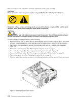
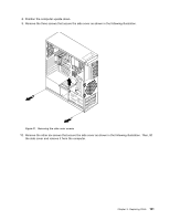
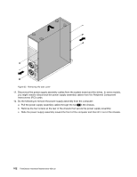
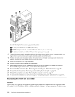
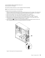
Figure 33. Removing the power supply assembly 13. Install the new power supply assembly into the chassis, make sure the screw holes in the new power supply assembly align with those in the chassis. 14. Install the four screws at the rear of the chassis to secure the new power supply assembly in place. 15. Push the power supply assembly cables through the hole 1 that is shown in Removing the power supply assembly. 16. Route the three power supply assembly cables through the two clips on the bottom of the hard disk drive cage following the inverse numerical sequence. Then, route the cables through the other two clips on the side of the hard disk drive cage following the numerical sequence. Chapter 9. Replacing FRUs 103
-
 1
1 -
2
-
3
-
4
-
5
-
6
-
7
-
8
-
9
-
10
-
11
-
12
-
13
-
14
-
15
-
16
-
17
-
18
-
19
-
20
-
21
-
22
-
23
-
24
-
25
-
26
-
27
-
28
-
29
-
30
-
31
-
32
-
33
-
34
-
35
-
36
-
37
-
38
-
39
-
40
-
41
-
42
-
43
-
44
-
45
-
46
-
47
-
48
-
49
-
50
-
51
-
52
-
53
-
54
-
55
-
56
-
57
-
58
-
59
-
60
-
61
-
62
-
63
-
64
-
65
-
66
-
67
-
68
-
69
-
70
-
71
-
72
-
73
-
74
-
75
-
76
-
77
-
78
-
79
-
80
-
81
-
82
-
83
-
84
-
85
-
86
-
87
-
88
-
89
-
90
-
91
-
92
-
93
-
94
-
95
-
96
-
97
-
98
-
99
-
100
-
101
-
102
-
103
-
 104
104 -
 105
105 -
 106
106 -
 107
107 -
 108
108 -
 109
109 -
 110
110 -
 111
111 -
 112
112 -
 113
113 -
 114
114 -
115
-
116
-
117
-
118
-
119
-
120
-
121
-
122
-
123
-
124
-
125
-
126
-
127
-
128
-
129
-
130
-
131
-
132
-
133
-
134
-
135
-
136
-
137
-
138
-
139
-
140
-
141
-
142
-
143
-
144
-
145
-
146
-
147
-
148
-
149
-
150
-
151
-
152
-
153
-
154
-
155
-
156
-
157
-
158
-
159
-
160
-
161
-
162
-
163
-
164
-
165
-
166
-
167
-
168
-
169
-
170
-
171
-
172
-
173
-
174
-
175
-
176
-
177
-
178
-
179
-
180
-
181
-
182
-
183
-
184
-
185
-
186
-
187
-
188
-
189
-
190
-
191
-
192
-
193
-
194
-
195
-
196
-
197
-
198
-
199
-
200
-
201
-
202
-
203
-
204
-
205
-
206
-
207
-
208
-
209
-
210
-
211
-
212
-
213
-
214
-
215
-
216
-
217
-
218
-
219
-
220
-
221
-
222
-
223
-
224
-
225
-
226
-
227
-
228
-
229
-
230
-
231
-
232
-
233
-
234
-
235
-
236
-
237
-
238
-
239
-
240
-
241
-
242
-
243
-
244
-
245
-
246
 |
 |
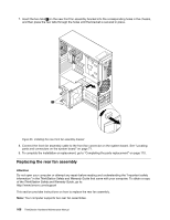
Figure 33. Removing the power supply assembly
13. Install the new power supply assembly into the chassis, make sure the screw holes in the new power
supply assembly align with those in the chassis.
14. Install the four screws at the rear of the chassis to secure the new power supply assembly in place.
15. Push the power supply assembly cables through the hole
1
that is shown in Removing the power
supply assembly.
16. Route the three power supply assembly cables through the two clips on the bottom of the hard disk
drive cage following the inverse numerical sequence. Then, route the cables through the other two clips
on the side of the hard disk drive cage following the numerical sequence.
Chapter 9
.
Replacing FRUs
103