Lenovo ThinkStation C20 Hardware Maintenance Manual - ThinkStation C20/C20x - Page 110
Replacing the front fan assembly
 |
View all Lenovo ThinkStation C20 manuals
Add to My Manuals
Save this manual to your list of manuals |
Page 110 highlights
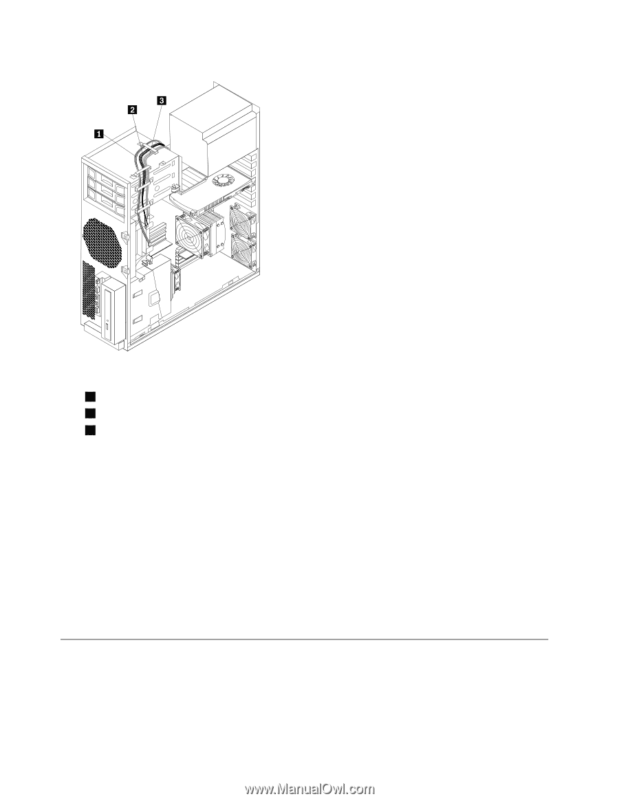
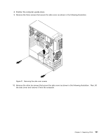
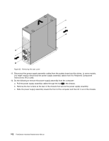
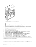
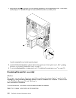
Figure 34. Routing the three power supply assembly cables 1 P3 cable (connected to the rear of the optical drive) 2 P5A/P5B cable (connected to an installed PCI card which requires power source) 3 P4 cable (connected to an installed PCI card which requires power source) 17. Connect the power supply assembly cables to the system board and all drives. In some models, you might need to connect the power supply assembly cables to the PCI cards. 18. Position the side cover into place so that the screw holes in the side cover align with those in the chassis. Reinstall the nine screws to secure the side cover. 19. Return the computer to its original position. 20. Reinstall the optical drive bracket into the chassis. 21. Slide the optical drive into the bracket from the front of the computer until it snaps into position. Reconnect the signal cable and the power cable to the optical drive. 22. Reinstall the PCI card holder. See "Removing and reinstalling the PCI card holder" on page 76. 23. Reinstall the front bezel. See "Removing and reinstalling the front bezel" on page 75. 24. Reinstall the computer cover. See "Removing the computer cover" on page 74 25. To complete the installation or replacement, go to "Completing the parts replacement" on page 110. Replacing the front fan assembly Attention Do not open your computer or attempt any repair before reading and understanding the "Important safety information" in the ThinkStation Safety and Warranty Guide that came with your computer. To obtain a copy 104 ThinkStation Hardware Maintenance Manual
-
 1
1 -
2
-
3
-
4
-
5
-
6
-
7
-
8
-
9
-
10
-
11
-
12
-
13
-
14
-
15
-
16
-
17
-
18
-
19
-
20
-
21
-
22
-
23
-
24
-
25
-
26
-
27
-
28
-
29
-
30
-
31
-
32
-
33
-
34
-
35
-
36
-
37
-
38
-
39
-
40
-
41
-
42
-
43
-
44
-
45
-
46
-
47
-
48
-
49
-
50
-
51
-
52
-
53
-
54
-
55
-
56
-
57
-
58
-
59
-
60
-
61
-
62
-
63
-
64
-
65
-
66
-
67
-
68
-
69
-
70
-
71
-
72
-
73
-
74
-
75
-
76
-
77
-
78
-
79
-
80
-
81
-
82
-
83
-
84
-
85
-
86
-
87
-
88
-
89
-
90
-
91
-
92
-
93
-
94
-
95
-
96
-
97
-
98
-
99
-
100
-
101
-
102
-
103
-
104
-
 105
105 -
 106
106 -
 107
107 -
 108
108 -
 109
109 -
 110
110 -
 111
111 -
 112
112 -
 113
113 -
 114
114 -
 115
115 -
116
-
117
-
118
-
119
-
120
-
121
-
122
-
123
-
124
-
125
-
126
-
127
-
128
-
129
-
130
-
131
-
132
-
133
-
134
-
135
-
136
-
137
-
138
-
139
-
140
-
141
-
142
-
143
-
144
-
145
-
146
-
147
-
148
-
149
-
150
-
151
-
152
-
153
-
154
-
155
-
156
-
157
-
158
-
159
-
160
-
161
-
162
-
163
-
164
-
165
-
166
-
167
-
168
-
169
-
170
-
171
-
172
-
173
-
174
-
175
-
176
-
177
-
178
-
179
-
180
-
181
-
182
-
183
-
184
-
185
-
186
-
187
-
188
-
189
-
190
-
191
-
192
-
193
-
194
-
195
-
196
-
197
-
198
-
199
-
200
-
201
-
202
-
203
-
204
-
205
-
206
-
207
-
208
-
209
-
210
-
211
-
212
-
213
-
214
-
215
-
216
-
217
-
218
-
219
-
220
-
221
-
222
-
223
-
224
-
225
-
226
-
227
-
228
-
229
-
230
-
231
-
232
-
233
-
234
-
235
-
236
-
237
-
238
-
239
-
240
-
241
-
242
-
243
-
244
-
245
-
246
 |
 |