Netgear MR314 Reference Guide - Page 105
Ethernet Cabling, Uplink Switches, Crossover Cables, and MDI/MDIX Switching
 |
UPC - 606449022148
View all Netgear MR314 manuals
Add to My Manuals
Save this manual to your list of manuals |
Page 105 highlights
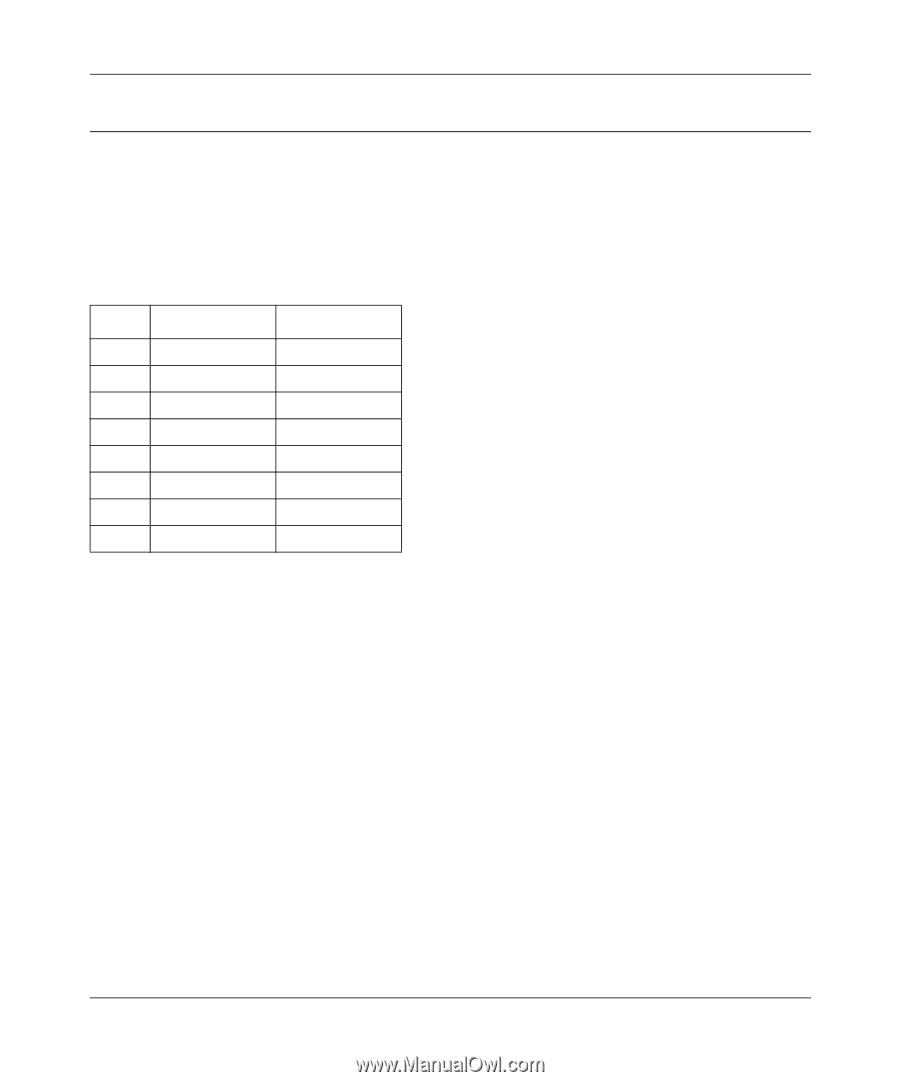
Reference Guide for the Model MR314 Cable/DSL Wireless Router Ethernet Cabling Although Ethernet networks originally used thick or thin coaxial cable, most installations currently use unshielded twisted pair (UTP) cabling. The UTP cable contains eight conductors, arranged in four twisted pairs, and terminated with an RJ45 type connector. A normal "straight-through" UTP Ethernet cable follows the EIA568B standard wiring and pinout as described in Table B-4. Table B-4. UTP Ethernet cable wiring, straight-through Pin Wire color Signal 1 Orange/White Transmit (Tx) + 2 Orange Transmit (Tx) - 3 Green/White Receive (Rx) + 4 Blue 5 Blue/White 6 Green Receive (Rx) - 7 Brown/White 8 Brown Uplink Switches, Crossover Cables, and MDI/MDIX Switching In the wiring table above, the concept of transmit and receive are from the perspective of the PC, which is wired as Media Dependant Interface (MDI). In this wiring, the PC transmits on pins 1 and 2. At the hub, the perspective is reversed, and the hub receives on pins 1 and 2. This wiring is referred to as Media Dependant Interface - Crossover (MDI-X). When connecting a PC to a PC, or a hub port to another hub port, the transmit pair must be exchanged with the receive pair. This exchange is done by one of three mechanisms: • Uplink switch Most hubs provide an Uplink switch which will exchange the pairs on one port, allowing that port to be connected to another hub using a normal Ethernet cable. Network and Routing Basics B-15
-
 1
1 -
2
-
3
-
4
-
5
-
6
-
7
-
8
-
9
-
10
-
11
-
12
-
13
-
14
-
15
-
16
-
17
-
18
-
19
-
20
-
21
-
22
-
23
-
24
-
25
-
26
-
27
-
28
-
29
-
30
-
31
-
32
-
33
-
34
-
35
-
36
-
37
-
38
-
39
-
40
-
41
-
42
-
43
-
44
-
45
-
46
-
47
-
48
-
49
-
50
-
51
-
52
-
53
-
54
-
55
-
56
-
57
-
58
-
59
-
60
-
61
-
62
-
63
-
64
-
65
-
66
-
67
-
68
-
69
-
70
-
71
-
72
-
73
-
74
-
75
-
76
-
77
-
78
-
79
-
80
-
81
-
82
-
83
-
84
-
85
-
86
-
87
-
88
-
89
-
90
-
91
-
92
-
93
-
94
-
95
-
96
-
97
-
98
-
99
-
 100
100 -
 101
101 -
 102
102 -
 103
103 -
 104
104 -
 105
105 -
 106
106 -
 107
107 -
 108
108 -
 109
109 -
 110
110 -
111
-
112
-
113
-
114
 |
 |