Netgear MR314 Reference Guide - Page 25
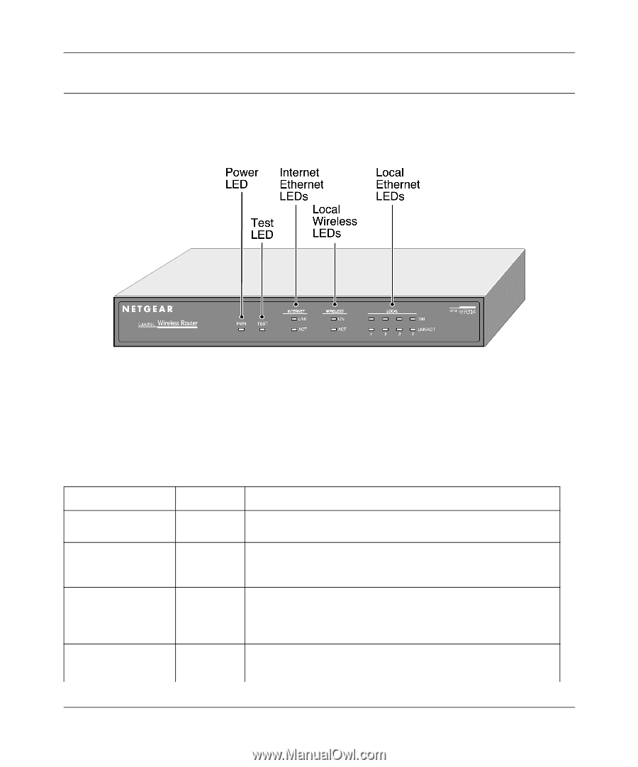
The Router’s Front Panel, the front panel of the Model MR314 router. These LEDs are green when lit
 |
UPC - 606449022148
View all Netgear MR314 manuals
Add to My Manuals
Save this manual to your list of manuals |
Page 25 highlights
Reference Guide for the Model MR314 Cable/DSL Wireless Router The Router's Front Panel The front panel of the Model MR314 router (Figure 2-1) contains status LEDs. Figure 2-1. MR314 Front Panel You can use some of the LEDs to verify connections. Table 2-1 lists and describes each LED on the front panel of the Model MR314 router. These LEDs are green when lit, except for the TEST LED which is amber. Table 2-1. LED Descriptions Label PWR (Power) TEST INTERNET (WAN) LNK ACT (Activity) WIRELESS (LAN) ON Activity On Off On Off Blinking On Blinking On Description Power is supplied to the router. Power is not supplied to the router. The system is not ready or has failed to start up. The system is ready and running. The system is initializing. The INTERNET port has detected a link with an attached device. Data is being transmitted or received by the INTERNET port. The wireless circuit is functional. Setting Up the Hardware 2-3
-
 1
1 -
2
-
3
-
4
-
5
-
6
-
7
-
8
-
9
-
10
-
11
-
12
-
13
-
14
-
15
-
16
-
17
-
18
-
19
-
 20
20 -
 21
21 -
 22
22 -
 23
23 -
 24
24 -
 25
25 -
 26
26 -
 27
27 -
 28
28 -
 29
29 -
 30
30 -
31
-
32
-
33
-
34
-
35
-
36
-
37
-
38
-
39
-
40
-
41
-
42
-
43
-
44
-
45
-
46
-
47
-
48
-
49
-
50
-
51
-
52
-
53
-
54
-
55
-
56
-
57
-
58
-
59
-
60
-
61
-
62
-
63
-
64
-
65
-
66
-
67
-
68
-
69
-
70
-
71
-
72
-
73
-
74
-
75
-
76
-
77
-
78
-
79
-
80
-
81
-
82
-
83
-
84
-
85
-
86
-
87
-
88
-
89
-
90
-
91
-
92
-
93
-
94
-
95
-
96
-
97
-
98
-
99
-
100
-
101
-
102
-
103
-
104
-
105
-
106
-
107
-
108
-
109
-
110
-
111
-
112
-
113
-
114
 |
 |