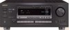
Onkyo TX-DS676 Owner Manual - Page 6
Audio equipment connections - no power
 |
View all Onkyo TX-DS676 manuals
Add to My Manuals
Save this manual to your list of manuals |
Page 6 highlights
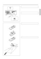
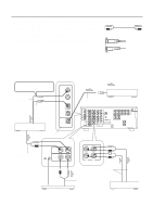
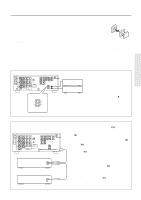
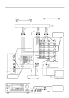
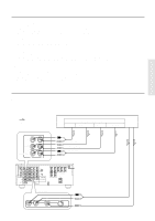
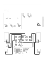
Audio equipment connections • Do not piug in the power cord until all connections have been made. • On each pair of input jacks, a red connector (marked R) corresponds to the right channel, and a white connector (marked L) to the left channel. • Please refer to the instruction manual of each component when making any con- nections. • Insert the plugs and connectors securely. Remember that improper connection can result in noise, poor performance, or damage to the equipment. • Do not bind audio connection calls with power cords and speaker cables. Doing so may degrade sound quality. Audio connection cable L (Left) L R (Right) R Improper Connection Insert completely Connect your player to COAXIAL or OPTICAL, whichever appropriate. OUTPUT (COAXIAL) Coaxial cable Optial fiber cable 1 DIGITAL INPUT COAXIAL 1 COAXIAL 2 OPTICAL 1 OUTPUT (DIGITAL) CD player OPTICAL 2 2 OPTICAL DIGITAL OUTPUT OUTPUT (ANALOG) TX-DS777 only :Signal Flow MD recorder / DAT etc... Optial fiber cable TX-DS777 / TX-DS676 DIGITAL INPUT R AMP IN COAXIAL 1 COAXIAL 2 OPTICAL 1 FRONT PRE OUT FRONT SUB WOOFER CENTER OPTICAL 2 SURROUND FRONT OPTICAL DIGITAL OUTPUT SUB WOOFER CENTER SURROUND MULTI CHANNEL INPUT R CD GND PHONO R L L L R L V S VIDEO-1 OUT IN VIDEO-2 VIDEO-3 OUT IN IN ANTENNA AM FM 75 DVD IN (REC) OUT TAPE MONITOR OUT V S IN (PLAY) R L VIDEO S VIDEO OSD SELECTOR TX-DS777 SURROUND SPEAKERS FRONT SPEAKERS A R L R L CENTER SPEAKER R L FRONT SPEAKERS B AC OUTLETS SWITCHED TOTAL 100W MAX. W REMOTE CONTROL Do not plug in the power cord until all connections have been made. Audio Connection Cable CD GND PHONO R L (REC) OUT TAPE IN (PLAY) R L Ground 3 Audio Connection Cable Turntable OUTPUT Audio Connection Cable OUTPUT (PLAY) INPUT (REC) Tape deck / MD recorder / DAT 6
-
 1
1 -
 2
2 -
 3
3 -
 4
4 -
 5
5 -
 6
6 -
 7
7 -
 8
8 -
 9
9 -
 10
10 -
 11
11 -
 12
12 -
13
-
14
-
15
-
16
-
17
-
18
-
19
-
20
-
21
-
22
-
23
-
24
-
25
-
26
-
27
-
28
-
29
-
30
-
31
-
32
-
33
-
34
-
35
-
36
-
37
-
38
-
39
-
40
-
41
-
42
-
43
-
44
-
45
-
46
-
47
-
48
-
49
-
50
-
51
-
52
-
53
-
54
-
55
-
56
-
57
-
58
-
59
-
60
-
61
-
62
-
63
-
64
 |
 |
