Onkyo TX-DS676 Owner Manual - Page 9
Connecting equipment with 5.1-channel output - us
 |
View all Onkyo TX-DS676 manuals
Add to My Manuals
Save this manual to your list of manuals |
Page 9 highlights
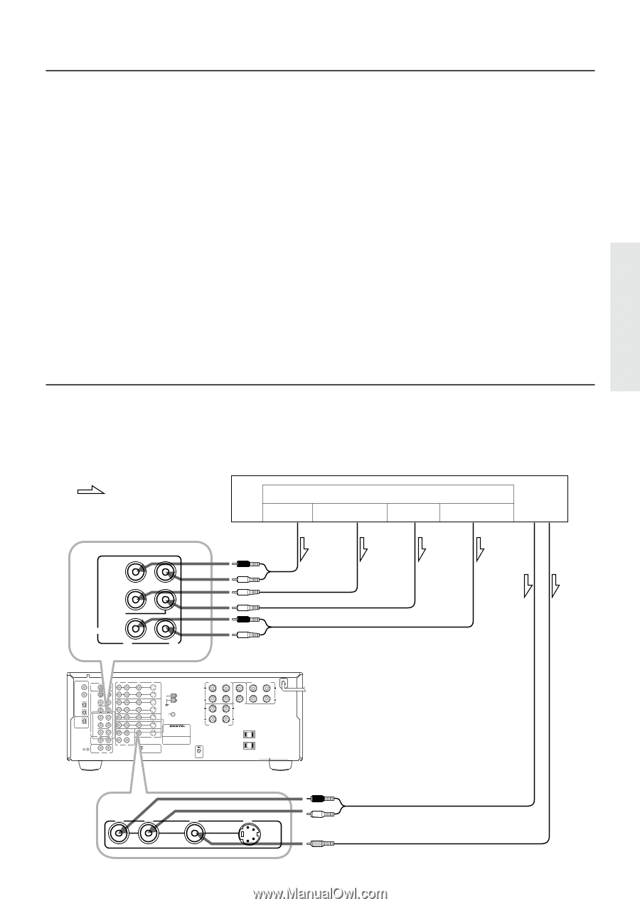
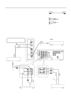
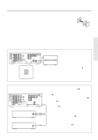
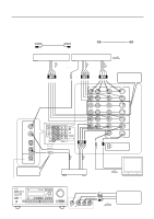
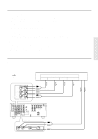
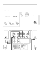
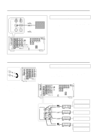
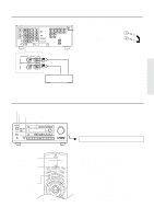
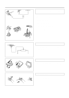
Video equipment connections 1. Digital audio connections This receiver has a powerful digital signal processor for use with DVD players, DAT decks, and CD players. The digital inputs, COAXIAL 1, 2 and OPTICAL 1, 2can be assigned to individual input selector buttons, so when an input selector button is pressed, the assigned digital input is used instead of the corresponding analog input. (See page 23,29.) 2. Connect your second video cassette deck. 3. Connect your DVD player to COAXIAL or OPTICAL, whichever appropriate. 4. OSD SELECTOR: Selects whether to output the OSD (On-Screen Display) information with the Video signals or the S-Video signals. Select "S VIDEO" when the monitor is connected via the S-Video terminal. 5. Connecting video equipment through S-video connectors • The signals input from the S IN jack will be output only to the S OUT jack; the signals input from the V IN jack will be output only to the V OUT jack. • For information on whether you need to connect either S or V jack or both of them, please refer to the instruction manual that came with your video equipment. 6. Connect your video camera or TV game machine to the VIDEO-4 / VIDEO CAM INPUT jacks. If a momaural video camera is used, connect its audio connection cable to " R(MONO)" audio jack. Notes: • When using a playback-only VCR, connect it to VIDEO 3 or VIDEO 4. If you connect it to VIDEO 1 or VIDEO 2, you need to make only the input connections. • This receiver can be used with only a monitor TV equipped with a video input or S video jack. • Interference may be caused between the TV and this receiver. If this interference occurs, place the receiver and the TV as far apart as possible. We do not recommend the use of a common TV/FM antenna (see antenna section). • Remove the protective cap attached to the DIGITAL INPUT/OUTPUT (OPTICAL) jack before making the connection. When this jack is not used, replace the protective cap. Connecting equipment with 5.1-channel output Decoder with 5.1 channel output You may connect the 5.1 channel outputs of an external decoder (such as MPEG decoder and DVD player) to the MULTI CHANNEL INPUTs of this unit. :Signal flow DVD player or a decoder with Multi (5.1) channel outputs Front Multi (5.1) channel outputs Subwoofer Center Surround FRONT SUB WOOFER CENTER SURROUND MULTI CHANNEL INPUT R L FRONT OUT SUBWOOFER OUT CENTER OUT SURROUND OUT DIGITAL INPUT R AMP IN COAXIAL 1 COAXIAL 2 OPTICAL 1 FRONT PRE OUT FRONT SUB WOOFER CENTER OPTICAL 2 SURROUND FRONT OPTICAL DIGITAL OUTPUT SUB WOOFER CENTER SURROUND MULTI CHANNEL INPUT R CD GMD PHONO R L L L R L V S VIDEO-1 OUT IN VIDEO-2 VIDEO-3 OUT IN IN ANTENNA AM FM 75 DVD IN (REC) OUT TAPE MONITOR OUT V S AV RECEIVER MODEL NO. TX-DS777 IN (PLAY) R L VIDEO S VIDEO OSD SELECTOR SURROUND SPEAKERS FRONT SPEAKERS A R L R L CENTER SPEAKER CAUTION: SPEAKER IMPEDANCE 6 OHMS MIN. / SPEAKER R L FRONT SPEAKERS B AC OUTLETS AC 120V 60Hz SWITCHED TOTAL 120W 1A MAX. REMOTE CONTROL TX-DS777 R L V S DVD IN AUDIO OUT VIDEO OUT 9
-
 1
1 -
2
-
3
-
 4
4 -
 5
5 -
 6
6 -
 7
7 -
 8
8 -
 9
9 -
 10
10 -
 11
11 -
 12
12 -
 13
13 -
 14
14 -
15
-
16
-
17
-
18
-
19
-
20
-
21
-
22
-
23
-
24
-
25
-
26
-
27
-
28
-
29
-
30
-
31
-
32
-
33
-
34
-
35
-
36
-
37
-
38
-
39
-
40
-
41
-
42
-
43
-
44
-
45
-
46
-
47
-
48
-
49
-
50
-
51
-
52
-
53
-
54
-
55
-
56
-
57
-
58
-
59
-
60
-
61
-
62
-
63
-
64
 |
 |