Onkyo TX-SR600 Owner Manual - Page 28
front panel.
 |
View all Onkyo TX-SR600 manuals
Add to My Manuals
Save this manual to your list of manuals |
Page 28 highlights
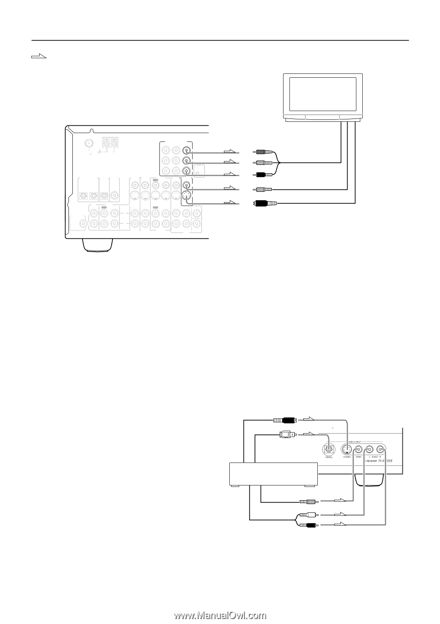
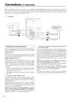
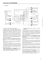
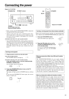
Connections (TX-SR600/600E) : Signal flow 6. TV monitor or projector (MONITOR OUT) ANTENNA FM AM 75 DIGITAL INPUT OPTICAL 2 1 DIGITAL DIGITAL OUTPUT INPUT OPTICAL COAXIAL COMPONENT VIDEO INPUT 2 INPUT 1 OUTPUT Y VIDEO 3 VIDEO 2 VIDEO 1 IN IN OUT IN PB REMOTE CONTROL PR DVD MONITOR IN OUT VIDEO CD IN L SUBWOOFER PRE OUT R TAPE OUT IN S VIDEO IN IN OUT IN FRONT SURR CENTER L L R VIDEO 3 VIDEO 2 VIDEO 1 R DVD SUB WOOFER Y PB PR Component video input Video input S Video input Note: When you connect a monitor to the MONITOR OUT S VIDEO jack, set the "OSD Output" setting of the "OSD Setup" menu to "S Video" to display the OSD Setup Menu on the monitor. For more details on how to change the setting, see "When the menu is not displayed on the monitor" on page 36. 6. Connecting a television monitor or projector (MONITOR OUT) Using an RCA video cable, connect the video input jack (composite) of the device to the MONITOR OUT VIDEO jack of the TX-SR600/ 600E. Or if the device has an S video input jack, connect it to the MONITOR OUT S VIDEO jack of the TX-SR600/600E using an S video cable. Or if the device has component video inputs, connect them to the bank of COMPONENT VIDEO OUTPUT jacks on the TX-SR600/600E. Note: Note that the Setup Menu will only be displayed on the monitor connected to MONITOR OUT and not those connected to the COMPONENT VIDEO OUTPUT jacks. 7. Connecting video camera, etc. (VIDEO 4 INPUT) Using an RCA video cable, connect the video output jack (composite) of the device to the VIDEO 4 VIDEO jack of the TXSR600/600E. Or if the device has an S video output jack, connect it to the VIDEO 4 S VIDEO jack of the TX-SR600/600E using an S video cable. Using an RCA audio cable, connect the audio output jack of the device to the VIDEO 4 AUDIO jacks of the TX-SR600/600E. Make sure that you properly connect the left channel to the L jack and the right channel to the R jack. If the device has an optical digital output, connect it to the VIDEO 4 DIGITAL jack of the TX-SR600/600E. The VIDEO 4 digital input is fixed to the OPTICAL input on the front panel. S Video output Digital output (optical) 7. Video camera/Video game (VIDEO 4 INPUT) Video output Left (white) Analog output Right (red) 28
-
 1
1 -
2
-
3
-
4
-
5
-
6
-
7
-
8
-
9
-
10
-
11
-
12
-
13
-
14
-
15
-
16
-
17
-
18
-
19
-
20
-
21
-
22
-
 23
23 -
 24
24 -
 25
25 -
 26
26 -
 27
27 -
 28
28 -
 29
29 -
 30
30 -
 31
31 -
 32
32 -
 33
33 -
34
-
35
-
36
-
37
-
38
-
39
-
40
-
41
-
42
-
43
-
44
-
45
-
46
-
47
-
48
-
49
-
50
-
51
-
52
-
53
-
54
-
55
-
56
-
57
-
58
-
59
-
60
-
61
-
62
-
63
-
64
-
65
-
66
-
67
-
68
-
69
-
70
-
71
-
72
-
73
-
74
-
75
-
76
-
77
-
78
-
79
-
80
 |
 |