Onkyo TX-SR600 Owner Manual - Page 7
Before using this unit, Supplied accessories - a v receiver
 |
View all Onkyo TX-SR600 manuals
Add to My Manuals
Save this manual to your list of manuals |
Page 7 highlights
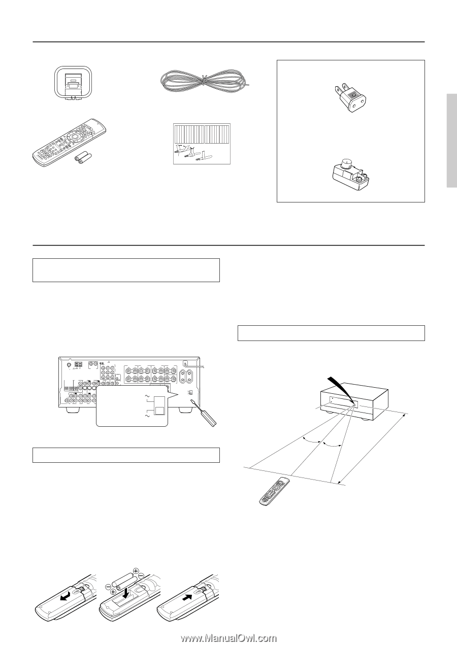
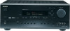
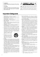
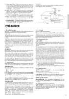
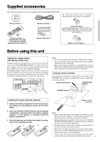
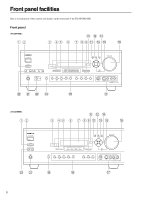
Supplied accessories Check that the following accessories are supplied with the TX-SR700/700E/600/600E. The following accessories may be available depending on the area which it was purchased. AM loop antenna × 1 RC-482M Remote controller × 1 TX-SR700/700E: RC-482M TX-SR600/600E: RC-480M Batteries (AA, R6 or UM-3) × 2 Front Left Front Left SP-B / Zone 2 Left SP-B / Zone 2 Left Front Right Front Right SP-B / Zone 2 Right SP-B / Zone 2 Right Surround Left Surround Left Surround Right Surround Right Center Center Surround Back Left Surround Back Left Zone 2 Left Zone 2 Left Surround Back Right Surround Back Right Zone 2 Right Zone 2 Right Front Left Front Left SP-B / Zone 2 Left SP-B / Zone 2 Left Front Right Front Right SP-B / Zone 2 Right SP-B / Zone 2 Right Surround Left Surround Left Surround Right Surround Right Center Center Surround Back Left Surround Back Left Zone 2 Left Zone 2 Left Surround Back Right Surround Back Right Zone 2 Right Zone 2 Right FM indoor antenna × 1 1 2 3 Speaker Cable Speaker cable label × 1 Conversion plug × 1 (Use this plug if the power cord plug of the TXSR700/700E/600/600E does not fit your AC outlet. Shape may vary depending on the area which it was purchased.) 75/300 Ω antenna adapter × 1 Before using this unit Setting the voltage selector (Worldwide models only) Worldwide models are equipped with a voltage selector so that you can set your TX-SR700/700E/600/600E to conform with local power supplies. Be sure to set this switch to match the voltage of the power supply in your area before plugging in the unit. Determine the proper voltage for your area: 220-230 V or 120 V. If the preset voltage is not correct for your area, insert a screwdriver into the groove in the switch and slide the switch all the way to the top (120 V) or bottom (220-230 V), whichever is appropriate. ANTENNA FM AM 75 R L PHONO IN GND COMPONENT VIDEO INPUT 2 INPUT 1 OUTPUT Y PB FRONT SPEAKERS L 27122974 CAUTION: SPEAKER IMPEDANCE 6 OHMS MIN. /SPEAKER ZONE 2 SPEAKERS SURROUND SPEAKERS L CENTER SPEAKER AC OUTLETS DIGITAL INPUT OPTICAL 2 1 DIGITAL VIDEO 3 OUTPUT COAXIAL IN OPTICAL VIDEO 2 OUT IN SUBWOOFER PRE OUT IN L R CD COAXIAL DIGITAL INPUT OUT IN IN OUT IN TAPE VIDEO 3 VIDEO 2 VIDEO 1 OUT IN DVD IN REMOTE CONTROL PR MONITOR OUT V R ZONE 2 12 V TRIGGER OUT S IR IN OUT IN FRONT SURR CENTER L VOLTAGE VIDEO 1 R DVD SUB WOOFER SELECTOR R FRONT SURROUND CENTER L ZONE 2 L SURROUND BACK SPEAKER PRE OUT R R AV RECEIVER 120 V MODEL NO. TX-SR700E SURROUND BACK SWITCHED TOTAL 100W MAX. 120 V VOLTAGE SELECTOR 220-230 V 220-230 V Notes: • Do not mix new batteries with old batteries or different kinds of batteries. • To avoid corrosion, remove the batteries if the remote controller will not be used for a long time. • Remove dead batteries immediately to avoid damage from corrosion. If the remote controller does not operate smoothly, remove the old batteries and replace them both with two new AA batteries. Using the remote controller Point the remote controller toward the remote control sensor. The STANDBY indicator lights up when the unit receives a signal from the remote controller. Remote control sensor TX-SR700/700E/ 600/600E STANDBY indicator Installing the remote controller batteries 1. Remove the battery compartment cover by pressing it and sliding it in the direction shown by the arrow below. 2. Insert two AA (R6 or UM-3) batteries into the battery compartment. Carefully follow the polarity diagram (positive (+) and negative (-) symbols) inside the battery compartment. 3. After the batteries are installed and seated correctly, replace the compartment cover. 1 2 3 30˚ 30˚ Approx. 16 feet (5 meters) RC-482M Notes: • Make sure that the remote control sensor is not subject to strong light such as direct sunlight or inverted fluorescent light for it may prevent proper operation of the remote controller. • Using another remote controller in the same room or using the TX-SR700/700E/600/600E near equipment that uses infrared rays may cause operational interference. • Do not put objects on the remote controller. Its buttons may be pressed by mistake and drain the batteries. • Make sure the audio rack doors do not have colored glass. Placing the TX-SR700/700E/600/600E behind such doors may prevent proper remote controller operation. • If there is any obstacle between the remote controller and the remote control sensor, the remote controller will not operate. 7
-
 1
1 -
 2
2 -
 3
3 -
 4
4 -
 5
5 -
 6
6 -
 7
7 -
 8
8 -
 9
9 -
 10
10 -
 11
11 -
 12
12 -
13
-
14
-
15
-
16
-
17
-
18
-
19
-
20
-
21
-
22
-
23
-
24
-
25
-
26
-
27
-
28
-
29
-
30
-
31
-
32
-
33
-
34
-
35
-
36
-
37
-
38
-
39
-
40
-
41
-
42
-
43
-
44
-
45
-
46
-
47
-
48
-
49
-
50
-
51
-
52
-
53
-
54
-
55
-
56
-
57
-
58
-
59
-
60
-
61
-
62
-
63
-
64
-
65
-
66
-
67
-
68
-
69
-
70
-
71
-
72
-
73
-
74
-
75
-
76
-
77
-
78
-
79
-
80
 |
 |