Panasonic HC-X1 Advanced Operating Manual - Page 77
Table of audio input patterns, To remove the external microphone, etc., from the AUDIO INPUT1
 |
View all Panasonic HC-X1 manuals
Add to My Manuals
Save this manual to your list of manuals |
Page 77 highlights
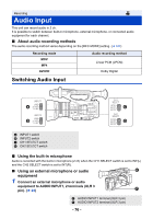
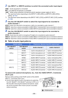
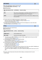
2 Use INPUT1 or INPUT2 switches to switch the connected audio input signal. LINE*1: Audio equipment is connected MIC*2: An external microphone is connected +48V*2: When using a phantom microphone (which requires a power supply of +48 V) *1 The input level varies depending on the [INPUT1 LINE LEVEL] or [INPUT2 LINE LEVEL] setting. (l 189) *2 The input level varies depending on the [INPUT1 MIC LEVEL] or [INPUT2 MIC LEVEL] setting. (l 189) 3 Use the CH1 SELECT switch to select the input signal to be recorded to audio channel 1. INT(L): Audio from the built-in microphone L (left) ch is recorded to audio channel 1. INPUT1: Audio from a device connected to AUDIO INPUT1 terminal (XLR 3 pin) is recorded to channel 1. INPUT2: Audio from a device connected to AUDIO INPUT2 terminal (XLR 3 pin) is recorded to channel 1. 4 Use the CH2 SELECT switch to select the input signal to be recorded to audio channel 2. INT(R): Audio from the built-in microphone R (right) ch is recorded to audio channel 2. INPUT1: Audio from a device connected to AUDIO INPUT1 terminal (XLR 3 pin) is recorded to channel 2. INPUT2: Audio from a device connected to AUDIO INPUT2 terminal (XLR 3 pin) is recorded to channel 2. ∫ Table of audio input patterns Switch setting CH1 SELECT switch CH2 SELECT switch INT(R) INT(L) INPUT1 INPUT2 INT(R) INPUT1 INPUT1 INPUT2 INT(R) INPUT2 INPUT1 INPUT2 Channel or terminal used for signal input Audio channel 1 Audio channel 2 built-in microphone Lch built-in microphone Lch built-in microphone Lch AUDIO INPUT1 terminal AUDIO INPUT1 terminal AUDIO INPUT1 terminal AUDIO INPUT2 terminal AUDIO INPUT2 terminal AUDIO INPUT2 terminal built-in microphone Rch AUDIO INPUT1 terminal AUDIO INPUT2 terminal built-in microphone Rch AUDIO INPUT1 terminal AUDIO INPUT2 terminal built-in microphone Rch AUDIO INPUT1 terminal AUDIO INPUT2 terminal To remove the external microphone, etc., from the AUDIO INPUT1, 2 terminals (XLR 3 pin) Remove while pushing on the PUSH section of the AUDIO INPUT1, 2 terminals (XLR 3 pin). ≥ Set the input signal to built-in microphone by switching the CH1 SELECT, CH2 SELECT switches to INT (L) or INT (R) after removing the external microphone. Audio will not be recorded when motion picture is recorded without switching. ヱヶヴラ A PUSH section - 77 -
-
 1
1 -
2
-
3
-
4
-
5
-
6
-
7
-
8
-
9
-
10
-
11
-
12
-
13
-
14
-
15
-
16
-
17
-
18
-
19
-
20
-
21
-
22
-
23
-
24
-
25
-
26
-
27
-
28
-
29
-
30
-
31
-
32
-
33
-
34
-
35
-
36
-
37
-
38
-
39
-
40
-
41
-
42
-
43
-
44
-
45
-
46
-
47
-
48
-
49
-
50
-
51
-
52
-
53
-
54
-
55
-
56
-
57
-
58
-
59
-
60
-
61
-
62
-
63
-
64
-
65
-
66
-
67
-
68
-
69
-
70
-
71
-
 72
72 -
 73
73 -
 74
74 -
 75
75 -
 76
76 -
 77
77 -
 78
78 -
 79
79 -
 80
80 -
 81
81 -
 82
82 -
83
-
84
-
85
-
86
-
87
-
88
-
89
-
90
-
91
-
92
-
93
-
94
-
95
-
96
-
97
-
98
-
99
-
100
-
101
-
102
-
103
-
104
-
105
-
106
-
107
-
108
-
109
-
110
-
111
-
112
-
113
-
114
-
115
-
116
-
117
-
118
-
119
-
120
-
121
-
122
-
123
-
124
-
125
-
126
-
127
-
128
-
129
-
130
-
131
-
132
-
133
-
134
-
135
-
136
-
137
-
138
-
139
-
140
-
141
-
142
-
143
-
144
-
145
-
146
-
147
-
148
-
149
-
150
-
151
-
152
-
153
-
154
-
155
-
156
-
157
-
158
-
159
-
160
-
161
-
162
-
163
-
164
-
165
-
166
-
167
-
168
-
169
-
170
-
171
-
172
-
173
-
174
-
175
-
176
-
177
-
178
-
179
-
180
-
181
-
182
-
183
-
184
-
185
-
186
-
187
-
188
-
189
-
190
-
191
-
192
-
193
-
194
-
195
-
196
-
197
-
198
-
199
-
200
-
201
-
202
-
203
-
204
-
205
-
206
-
207
-
208
-
209
-
210
-
211
-
212
-
213
-
214
-
215
-
216
-
217
-
218
-
219
-
220
-
221
-
222
-
223
-
224
-
225
-
226
-
227
-
228
-
229
-
230
-
231
-
232
-
233
-
234
-
235
 |
 |
