Ryobi GD201 Operation Manual - Page 31
Safety, Sensor, Screw, Safety Sensor, Wires, Insulated, Staples, Power, Green, Transmitter, Receiver
 |
View all Ryobi GD201 manuals
Add to My Manuals
Save this manual to your list of manuals |
Page 31 highlights
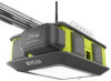
INSTALLATION NOTE: The top of the sensor should be between four and six inches above the floor. NOTE: The receiving sensor has a green LED. Ensure that the lens on this sensor is not exposed to direct sunlight. Mark the position of the hole in the bracket. Secure brackets in place using nails or drill 3/16 in. pilot holes and secure with lag screws. Tighten screws with an 11 mm socket. NOTE: Use lag screws and concrete anchors (not included) when installing the brackets into concrete, brick, or other masonry. WARNING: To avoid the risk of death, electric shock, or serious personal injury ensure that the garage door opener is unplugged and the battery pack is removed before wiring the sensors. WARNING: Connect the sensors using low voltage wires provided only to prevent the risk of electric shock or serious personal injury. Route the wires from the sensors to the door sensor wire terminals. Attach the wires to the wall and ceiling using the insulated staples. Secure the staples to the wall and ceiling using a hammer. Using wire strippers, strip 1/2 in. of insulation from the ends of each wire. To install or remove wires from a wire terminal, depress the tab beside the terminal. Twist the gray striped wires from both sensors together and insert them into the right door sensor terminal marked with G. Safety Sensor (Receiver) Arrow Safety Sensor (Transmitter) Safety Sensor LED (Green) Safety Sensor LED (Red) Lag Screw Fig. 52 Insulated Staples Fig. 53 31 - English Safety Sensor Fig. 54 Power Head Wires Fig. 55
-
 1
1 -
2
-
3
-
4
-
5
-
6
-
7
-
8
-
9
-
10
-
11
-
12
-
13
-
14
-
15
-
16
-
17
-
18
-
19
-
20
-
21
-
22
-
23
-
24
-
25
-
 26
26 -
 27
27 -
 28
28 -
 29
29 -
 30
30 -
 31
31 -
 32
32 -
 33
33 -
 34
34 -
 35
35 -
 36
36 -
37
-
38
-
39
-
40
-
41
-
42
-
43
-
44
-
45
-
46
-
47
-
48
-
49
-
50
-
51
-
52
-
53
-
54
-
55
-
56
-
57
-
58
-
59
-
60
-
61
-
62
-
63
-
64
-
65
-
66
-
67
-
68
-
69
-
70
-
71
-
72
-
73
-
74
-
75
-
76
-
77
-
78
-
79
-
80
-
81
-
82
-
83
-
84
-
85
-
86
-
87
-
88
-
89
-
90
-
91
-
92
-
93
-
94
-
95
-
96
-
97
-
98
-
99
-
100
-
101
-
102
-
103
-
104
-
105
-
106
-
107
-
108
-
109
-
110
-
111
-
112
-
113
-
114
-
115
-
116
-
117
-
118
-
119
-
120
-
121
-
122
-
123
-
124
-
125
-
126
-
127
-
128
-
129
-
130
-
131
-
132
-
133
-
134
-
135
-
136
-
137
-
138
-
139
-
140
-
141
-
142
-
143
-
144
-
145
-
146
-
147
-
148
-
149
-
150
-
151
-
152
-
153
-
154
-
155
-
156
-
157
-
158
-
159
-
160
 |
 |
