Sony DVWM2000 Product Manual (dvwm2000 installation manual) - Page 11
Attaching the rack angles handles, Attaching the inner rails
 |
View all Sony DVWM2000 manuals
Add to My Manuals
Save this manual to your list of manuals |
Page 11 highlights
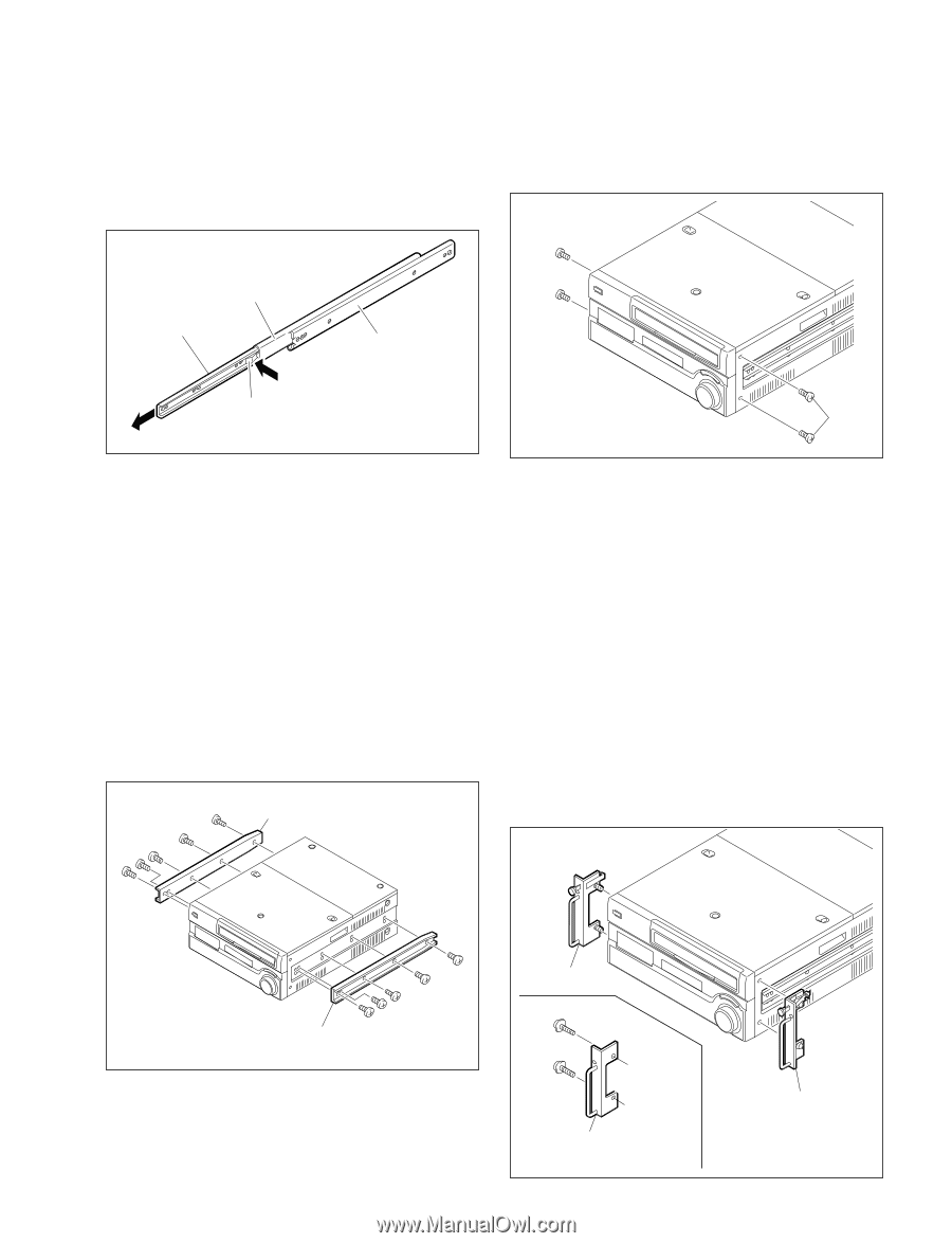
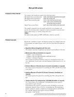
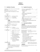
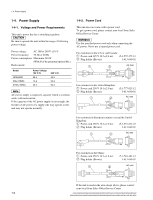
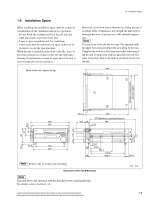
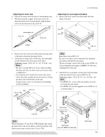
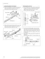
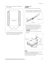
1-6. Rack Mounting . Attaching the inner rails 4. Pull out the inner rails from the two intermediate rails. 5. While pressing the stopper of the inner rail in the direction of the arrow A in the figure, pull the inner rail out in the direction of the arrow B. . Attaching the rack angles (handles) 8. Remove the four screws from both sides (left and right) of the unit. Intermediate rail Inner rail A Stopper B Outer rail B4 x 6 B4 x 6 B4 x 6 6. Remove the ten screws from both sides (left and right) of the unit as shown in the figure below. 7. Attach the two inner rails to both sides (left and right) of unit with the removed screws in the step 6. Tightening torque: 120 x 10_2 N . m {12.2 kgf . cm} m . Be sure to use the (B4 x 6) screws when attaching the inner rail. The use other-sized screws may cause a malfunction. . Pay attention not to fasten the screws to the screw holes other than actually used screw holes for fixing the inner rails on both sides of the unit. If unnecessary screws are fastened, rack mounting will be unenabled. B4 x 6 Inner rail n Keep these screws (B4 x 6). Be sure to use these screws when directly fixing the side panels without the rack angles. The use of longer screws such as the screws (PSW 4 x 16) for fixing the rack angles of RMM-130 will cause a malfunction of the unit. 9. Attach the two rack angles to both sides (left and right) of the unit with the four screws (PSW4 x 16). Tightening torque: 120 x 10_2 N . m {12.2 kgf . cm} n . For RMM-131, screws with stop washers are used for fixing the rack angles. . For RMM-130, use the supplied screws PSW4 x 16 as shown in Fig. 1. Inner rail B4 x 6 Rack angle PSW4 x 16 n When replacing a 5U size Sony VTR with this unit, attach the inner rails to the low position, so that the bottom of the unit becomes same as that of the 5U size VTR. PSW 4 x 16 Rack angle Fig.1 For RMM-130 (Left side) HDW-2000/M2000/M2000P/S2000/S2000P/M2100/M2100P, DVW-2000/2000P/M2000/M2000P MSW-2000/A2000/A2000P/M2000/M2000P/M2000E/M2000EP/M2100/M2100P/M2100E/M2100EP Rack angle 1-5
-
 1
1 -
2
-
3
-
4
-
5
-
 6
6 -
 7
7 -
 8
8 -
 9
9 -
 10
10 -
 11
11 -
 12
12 -
 13
13 -
 14
14 -
 15
15 -
 16
16 -
17
-
18
-
19
-
20
-
21
-
22
-
23
-
24
-
25
-
26
-
27
-
28
-
29
-
30
-
31
-
32
-
33
-
34
-
35
-
36
-
37
-
38
-
39
-
40
-
41
-
42
-
43
-
44
-
45
-
46
-
47
-
48
 |
 |