Sony DVWM2000 Product Manual (dvwm2000 installation manual) - Page 21
Switch Settings on Connector Panel
 |
View all Sony DVWM2000 manuals
Add to My Manuals
Save this manual to your list of manuals |
Page 21 highlights
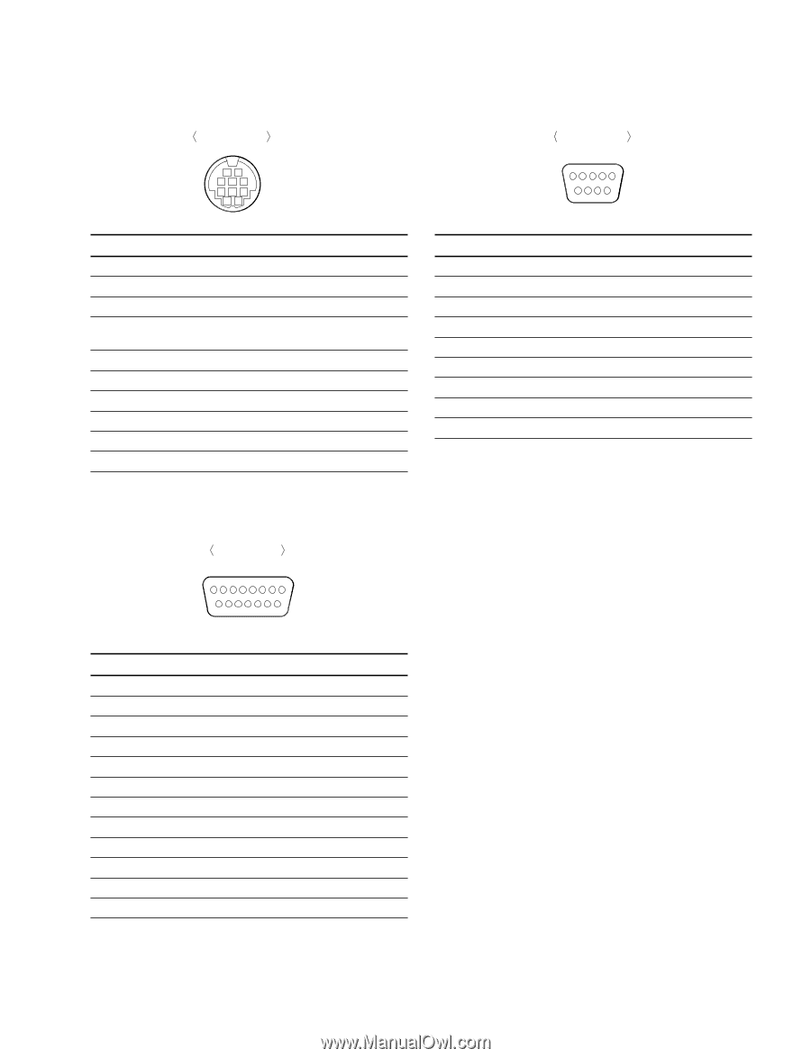
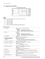
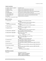
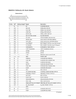
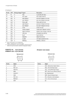
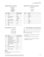
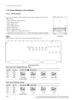
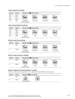
1-8. Signal Inputs and Outputs 1-9. Switch Settings on Connector Panel CONTROL PANEL: 10-pin (female) External view 1 2 3 5 6 8 9 10 Pin No. Signal 1 +21 V 2 +21 V 3 KEY TX (+) (Output) 4 FRONT/REAR 5 KEY TX (_) (Output) 6 KEY RX (+) (Input) 7 GND 8 KEY RX (_) (INPUT) 9 GND 10 GND Terminal voltage (V) +21 V +21 V RS422 +5: FRONT 0: REAR RS422 RS422 RS422 -- -- VIDEO CONTROL / (OPTION): 9-pin (female) External view 5 1 Pin No. 1 2 3 4 5 6 7 8 9 96 Signal GND RM TX (_) RM RX (+) GND -- GND RM TX (+) RM RX (_) GND VIDEO CONTROL: 15-pin (male) External view 1 8 9 15 Pin No. Signal Terminal voltage (V) 1 SYNC CONT (Input) _5 to +5 2 HUE CONT (Input) _5 to +5 3 SC CONT (Input) _5 to +5 4 VIDEO LEVEL CONT (Input) _5 to +5 5 SETUP CONT (Input) _5 to +5 6 CHROMA LEVEL CONT (Input) _5 to +5 7 REG _12V (Output) _12 8 GND -- 9 to 12 13 14 NC Y/C DELAY CONT (Input) NC -- _5 to +5 -- 15 REG +12V (Output) +12 n This connector exclusively connects the TBC remote controller BVR-50. 1-9. Switch Settings on Connector Panel When the unit is installed, be sure to perform the following setup. Refer to the operation manual "Section 2 Location and Function of Parts" for setup. . Analog audio input level/600 Z termination switches (Recorder only) . 75 Z termination switch of reference video input . 75 Z termination switch of composite video input (DVW/MSW recorder only) HDW-2000/M2000/M2000P/S2000/S2000P/M2100/M2100P, DVW-2000/2000P/M2000/M2000P MSW-2000/A2000/A2000P/M2000/M2000P/M2000E/M2000EP/M2100/M2100P/M2100E/M2100EP 1-15
-
 1
1 -
2
-
3
-
4
-
5
-
6
-
7
-
8
-
9
-
10
-
11
-
12
-
13
-
14
-
15
-
 16
16 -
 17
17 -
 18
18 -
 19
19 -
 20
20 -
 21
21 -
 22
22 -
 23
23 -
 24
24 -
 25
25 -
 26
26 -
27
-
28
-
29
-
30
-
31
-
32
-
33
-
34
-
35
-
36
-
37
-
38
-
39
-
40
-
41
-
42
-
43
-
44
-
45
-
46
-
47
-
48
 |
 |