Sony DVWM2000 Product Manual (dvwm2000 installation manual) - Page 14
Attaching the Clamp Filters HDW, Series Only
 |
View all Sony DVWM2000 manuals
Add to My Manuals
Save this manual to your list of manuals |
Page 14 highlights
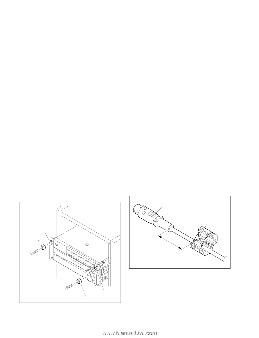
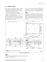
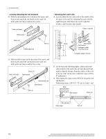
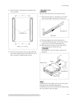
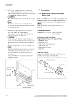
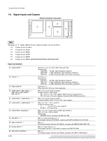
1-6. Rack Mounting 1-7. Connection 21. Slide the unit in and out from the rack about three times and check that the slide rails move smoothly. If they are not smoothly, demount the unit and go back to "Attaching the outer rails" (step 12). c When demounting the unit, carry it by the two persons or more. n This unit does not have the feet at this operating. Put down the unit on the floor or other, being careful not to damage the unit. 1-7. Connection 1-7-1. Attaching the Clamp Filters (HDW Series Only) In the case of HDW series, to make the unit compliant with the EMC regulation, be sure to attach the clamp filter on each XLR cable connected to the following connectors. n In the case of DVW series and MSW series, it is not required. 22. Push the unit in the depths of the rack. The unit is fixed to the rack by the lock mechanism. Attempt to pull the rack angles and confirm that the unit cannot be pulled out of the rack. w When installing the unit in an Outside Broadcasting van, be sure to fix the unit to the rack using the screws and ornamental washers supplied with the rack mount kit. Tightening torque: 120 x 10_2 N . m {12.2 kgf . cm} n When the unit is not fixed to the rack or the clearances between the rack angle and rack are existed, it is necessary to perform the adjustment for the lock mechanism. Refer to the RMM-131 installation guide for more detailed information. Supplied Accessories Clamp filter (1-543-798-21) 6 pieces (Recorder) or 4 pieces (Player) Connectors of the XLR Cables Required Attachment of the Clamp Filters . MONITOR OUT L . MONITOR OUT R . TIME CODE IN (Recorder only) . TIME CODE OUT . CUE IN (Recorder only) . CUE OUT Attaching Position Snap on the clamp filter at the place 50 to 150 mm away from the connector plug of the XLR cable. XLR connector plug Release button Ornamental washer RK5 x 14 50 to 150 mm Clamp filter 1-8 RK5 x 14 Release button Ornamental washer HDW-2000/M2000/M2000P/S2000/S2000P/M2100/M2100P, DVW-2000/2000P/M2000/M2000P MSW-2000/A2000/A2000P/M2000/M2000P/M2000E/M2000EP/M2100/M2100P/M2100E/M2100EP
-
 1
1 -
2
-
3
-
4
-
5
-
6
-
7
-
8
-
 9
9 -
 10
10 -
 11
11 -
 12
12 -
 13
13 -
 14
14 -
 15
15 -
 16
16 -
 17
17 -
 18
18 -
 19
19 -
20
-
21
-
22
-
23
-
24
-
25
-
26
-
27
-
28
-
29
-
30
-
31
-
32
-
33
-
34
-
35
-
36
-
37
-
38
-
39
-
40
-
41
-
42
-
43
-
44
-
45
-
46
-
47
-
48
 |
 |