Sony DVWM2000 Product Manual (dvwm2000 installation manual) - Page 22
-1., APR-52 Board
 |
View all Sony DVWM2000 manuals
Add to My Manuals
Save this manual to your list of manuals |
Page 22 highlights
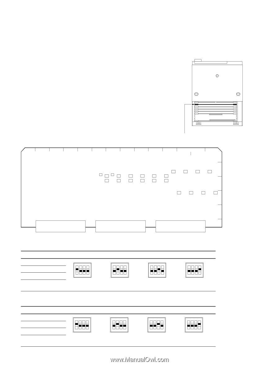
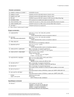
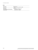
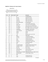
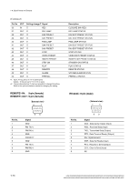
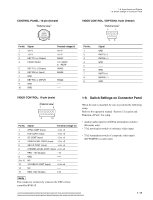
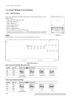
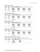
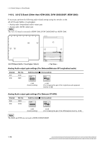
1-10. Switch Settings on Circuit Boards 1-10. Switch Settings on Circuit Boards 1-10-1. APR-52 Board If necessary, perform the following audio-related settings using the switches on the APR-52 board. . Audio input level *1 (Recorder only) . Audio input headroom *2 . Audio output level *1 . Audio output headroom *2 . Monitor output level *1 . Monitor output headroom *2 . Monitor output level, fixed/variable selection *1: Select the level for each channel from +4, 0, _3, _20 dBm. (Factory settings: +4 dBm for each channel) *2: Select the headroom for each channel from 20, 18, 16, 12 dB. (Factory settings: 20 dB for each channel) n Refer to Section 1-16 for removing and reattaching the plug-in boards. < Top View > A B C D E F G H J K L APR-52 N P A M 1 S901 S1001 S401 S301 S201 S101 2 S900 S1000 S800 S700 S600 S500 S902 S1002 S801 S701 S601 S501 S400 S300 S200 3 S100 4 5 6 APR-52 Board (Side A) Audio input level settings (Recorder only) Channel CH1 CH2 CH3 CH4 Ref. No. S100 S200 S300 S400 Switches state (\ : Knob position) N O N O 4 3 2 1 4 3 2 1 +4 dBm/600 Z (Factory setting) 0 dBm/600 Z 1 O 2 N 3 _3 dBm/600 Z 4 1 O 2 N _20 dBm/600 Z 3 4 Audio input headroom settings Channel CH1 CH2 CH3 CH4 1-16 Ref. No. S101 S201 S301 S401 Switches state (\ : Knob position) N O N O N O N O 4 3 2 1 4 3 2 1 4 3 2 1 4 3 2 1 20 dB (Factory setting) 18 dB 16 dB 12 dB HDW-2000/M2000/M2000P/S2000/S2000P/M2100/M2100P, DVW-2000/2000P/M2000/M2000P MSW-2000/A2000/A2000P/M2000/M2000P/M2000E/M2000EP/M2100/M2100P/M2100E/M2100EP
-
 1
1 -
2
-
3
-
4
-
5
-
6
-
7
-
8
-
9
-
10
-
11
-
12
-
13
-
14
-
15
-
16
-
 17
17 -
 18
18 -
 19
19 -
 20
20 -
 21
21 -
 22
22 -
 23
23 -
 24
24 -
 25
25 -
 26
26 -
 27
27 -
28
-
29
-
30
-
31
-
32
-
33
-
34
-
35
-
36
-
37
-
38
-
39
-
40
-
41
-
42
-
43
-
44
-
45
-
46
-
47
-
48
 |
 |