Sony DVWM2000 Product Manual (dvwm2000 installation manual) - Page 7
Installation - dvw m2000 installation manual
 |
View all Sony DVWM2000 manuals
Add to My Manuals
Save this manual to your list of manuals |
Page 7 highlights
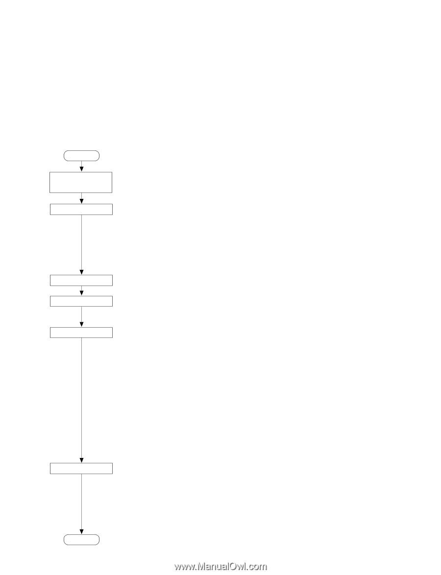
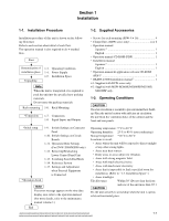
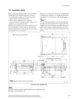
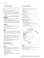
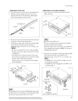
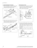
Section 1 Installation 1-1. Installation Procedure 1-2. Supplied Accessories Installation procedure of this unit is shown on the following flowchart. Refer to each section about detail of each flow. The operation manual is also required to do *-marked flow. Start Determination of installation place Unpacking 1-3. Operating Conditions 1-4. Power Supply 1-5. Installation Space n When the unit is transported, it is required to pack the unit into the specified new packing materials. Do not reuse the packing materials. Rack mounting 1-6. Rack Mounting *Connection 1-7. Connection 1-8. Signal Inputs and Outputs . Screws for rack mounting (PSW 4 x 16 4 . Clamp filters (HDW series only 4 or 6 . Operation manual Japanese *1 1 English 1 . Operation manual CD-ROM (PDF 1 . Installation manual Japanese*1 1 English 1 . Operation manual & application software CD-ROM (PDF)*2 1 . BKMW-E3000 Installation manual*2 1 *1: Supplied with DVW series only. *2: Supplied with MSW-M2000E/M2000EP/M2100E/ M2100EP only. 1-3. Operating Conditions c Good air circulation is essential to prevent internal heat buildup. Place the unit in location with sufficient air circulation. Do not block the ventilation holes of the cabinet and the front and rear panels. *Initial setup 1-9. Switch Settings on Connector Panel 1-10. Switch Settings on Circuit Boards 1-11. Operation Mode Settings (For DVW-2000/M2000 only) 1-12. Removing/Reattaching Lower Control Panel Unit 1-13. Switching Search Dial Mode 1-14. Reference System 1-15. Settings and Adjustment when External Equipment is Connected *Operation check n If an error message appears on the time data display area, refer to the operation manual. (For more details, refer to the maintenance manual volume-1.) End Operating temperature: 5 dC to 40 dC Operating humidity: 25 % to 80 % (non-condensing) Storage temperature: _20 dC to 60 dC Locations to avoid: . Areas where the unit will be exposed to direct sunlight of any other strong lights. . Areas near heat sources. . Dusty areas or areas subject to vibration. . Areas with strong magnetic field. . Areas with much electrical noise. . Areas with much static electricity. . Areas that is impossible to find a specified room for installation. (Refer to "1-5. Installation Space".) . Areas windtight. Tilt allowance: Within 30d (Do not slant the front and rear of the unit more than 30d.) c Fix the unit securely to avoid drop when the unit is operat- ed at not-horizontal place. HDW-2000/M2000/M2000P/S2000/S2000P/M2100/M2100P, DVW-2000/2000P/M2000/M2000P MSW-2000/A2000/A2000P/M2000/M2000P/M2000E/M2000EP/M2100/M2100P/M2100E/M2100EP 1-1
-
 1
1 -
 2
2 -
 3
3 -
 4
4 -
 5
5 -
 6
6 -
 7
7 -
 8
8 -
 9
9 -
 10
10 -
 11
11 -
 12
12 -
13
-
14
-
15
-
16
-
17
-
18
-
19
-
20
-
21
-
22
-
23
-
24
-
25
-
26
-
27
-
28
-
29
-
30
-
31
-
32
-
33
-
34
-
35
-
36
-
37
-
38
-
39
-
40
-
41
-
42
-
43
-
44
-
45
-
46
-
47
-
48
 |
 |