Sony DVWM2000 Product Manual (dvwm2000 installation manual) - Page 34
-3., System Phase Alignment, 15-4., Setup Menu Settings, 15-5., Other Settings - dvw m2000 service manual
 |
View all Sony DVWM2000 manuals
Add to My Manuals
Save this manual to your list of manuals |
Page 34 highlights
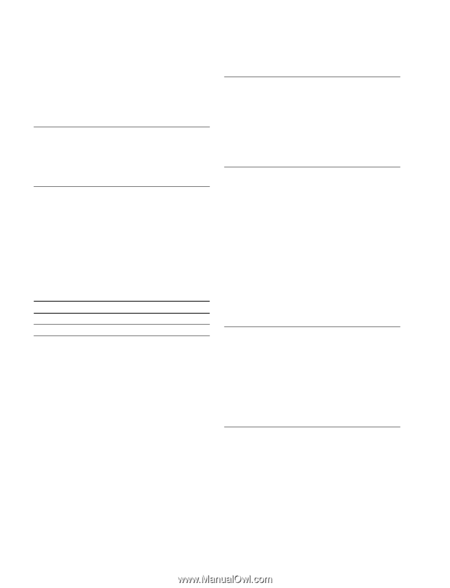
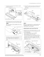
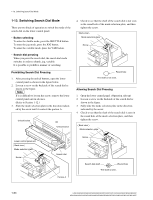
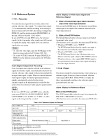
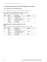
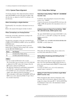
1-15. Settings and Adjustment when External Equipment is Connected 1-15-3. System Phase Alignment 1-15-4. Setup Menu Settings An external reference video signal and analog composite signal (DVW/MSW recorder only) must be input to this unit after they are adjusted so that SC-H conforms to the specifications. When Connecting to a Digital Switcher Fundamentally, the system phase adjustment is not necessary. Refer to the manual of the digital switcher for details. When Connecting to an Analog Switcher Perform the system phase adjustment according to the manual of the analog switcher. To adjust the system phase of this unit, open the P3 page (VIDEO OUT CONTROL2 & MISC) and use the MULTI CONTROL knob. When adjusting (i.e. changing the settings), press the button below to blink the current setting value, and then turn the MULTI CONTROL knob. Button F1 F2 Item (Display) SYSTEM SYNC PHASE (SYNC) SYSTEM SUBCARRIER PHASE (SC) m . Be sure to adjust in PB mode for the recorder. The system phase does not change even if the SYNC/SC is adjusted in the REC mode, but it changes when the REC mode is shifted to the PB mode. . The playback sound may be momentarily interrupted if the SYNC/SC is adjusted during tape playback. . For the HDW series, the system phase of HD input and output can be adjusted in function menu Page 3. . The system phase of SD output of both HDW, DVW and MSW series can be adjusted in ITEM-719 and -720 of the extended setup menu. Video/Sync Delay Setting "ITEM-701" (DVW/MSW recorder only) Commonly, when integrating the menu into the editing system, set to "VIDEO". To prevent the picture shift during EE/PB switching in the VTR-to-VTR edit operation, this setup menu is also set to "VIDEO". Analog Component Signal Format Setting "ITEM709" (59.94 Hz mode, 525/60 system only) The input (SUB-ITEM-0) and output (SUB-ITEM-1) sides are set to "D-1" or "B-CAM" according to the operating system, respectively. n For the HDW series and MSW-M2100/M2100P/M2100E/ M2100EP, set only output side. 1-15-5. Other Settings When make the following settings, please contact your local Sony Sales Office/Service Center. Setting When Combining with Editing Control Unit PVE-500 When setting initial speed to extra slow playback at less than ± 0.03 time speed duaring DMC editing the unit as a player, the setup extended menu ITEM-F34 setting should be changed. For detail of ITEM-F series, refer to the maintenance manual volume-1 (Section 1). Setting of Audio Channel and Data Length Mode (MSW recorder only) When changing the audio channel configuration of this unit from 16 bit x 8 ch (factory setting) to 24 bit x 4 ch, change the setting of the menu M371 : DATA LENGTH in the maintenance mode, refer to the maintenance manual volume-1 (Section 3). 1-28 HDW-2000/M2000/M2000P/S2000/S2000P/M2100/M2100P, DVW-2000/2000P/M2000/M2000P MSW-2000/A2000/A2000P/M2000/M2000P/M2000E/M2000EP/M2100/M2100P/M2100E/M2100EP
-
 1
1 -
2
-
3
-
4
-
5
-
6
-
7
-
8
-
9
-
10
-
11
-
12
-
13
-
14
-
15
-
16
-
17
-
18
-
19
-
20
-
21
-
22
-
23
-
24
-
25
-
26
-
27
-
28
-
 29
29 -
 30
30 -
 31
31 -
 32
32 -
 33
33 -
 34
34 -
 35
35 -
 36
36 -
 37
37 -
 38
38 -
 39
39 -
40
-
41
-
42
-
43
-
44
-
45
-
46
-
47
-
48
 |
 |