Sony DVWM2000 Product Manual (dvwm2000 installation manual) - Page 17
Remote connectors, Output connectors, Input/Output connector - dvw 2000 manual
 |
View all Sony DVWM2000 manuals
Add to My Manuals
Save this manual to your list of manuals |
Page 17 highlights
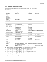
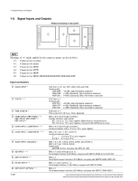
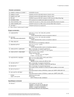
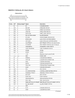
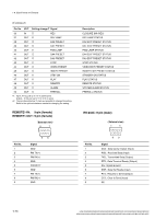
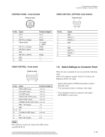
1-8. Signal Inputs and Outputs Remote connectors 4 REMOTE 2 PARALLEL I/O (50P) *** D-SUB 50P connector 4 REMOTE1-IN (9P) D-SUB 9P connector (RS-422A interface), Remote control 4 REMOTE1-OUT (9P) D-SUB 9P connector (RS-422A interface), Remote control 4 RS-232C D-SUB 9P connector (RS-232C interface) for ISR (Interactive Status Reporting) 4 CONTROL PANEL 10P connector for an outside control panel connection only 4 VIDEO CONTROL (15P) D-SUB 15P connector for a TBC remote controller (BVR-50) exclusive connection 4 VIDEO CONTROL (9P) *3 D-SUB 9P connector for a TBC remote controller (HKDV-900) connection 4 (OPTION) *4, 5 D-SUB 9P connector for an optional kit *** : Refer to Optional "Interface manual" for details. Output connectors 1 AUDIO OUTPUT 1 CUE OUT (Excl. MSW-2000/A2000/A2000P) 1 TIME CODE OUT 1 MONITOR OUTPUT 2 VIDEO OUTPUT, COMPOSITE 2 VIDEO OUTPUT, COMPONENT 3 AUDIO OUTPUT (AES/EBU) 5 HD SDI OUTPUT *3 5 SDI OUTPUT 5 SDTI-CP OUTPUT *5 5 SDTI OUTPUT (OPTION) *3 PHONE (Upper control panel) XLR 3-pin x 4 (1 set : CH1, CH2, CH3, and CH4) Analog audio +4 dBm (Standard) (600 Z load), low impedance, balanced XLR 3-pin x 4 (1 set : CH1, CH2, CH3, and CH4) Analog audio +4 dBm (Standard) (600 Z load), low impedance, balanced XLR 3-pin x 1 Time code 2.2 V p-p, low impedance, balanced XLR 3-pin x 2 (1 set : L and R) Analog audio +4 dBm (Standard) (600 Z load), low impedance, balanced BNC x 3 (including 1 for character superimpose) Analog composite video 1.0 V p-p, 75 Z, sync negative BNC x 3 (1 set : Y, R-Y, and B-Y) Analog component video Y : 1.0 V p-p, 75 Z, sync negative R-Y/B-Y : 0.7 V p-p, 75 Z BNC x 4 (1 set : CH1/2, CH3/4, CH5/6, and CH7/8) or BNC x 2 (1 set : CH1/2, CH3/4) Digital audio AES/EBU format, complies with AES-3id-1995 BNC x 3 (including 1 for character superimpose) Serial digital interface (270 Mbit/s), complies with SMPTE 292 BNC x 3 (including 1 for character superimpose) Serial digital interface (270 Mbit/s), complies with SMPTE 259M & ITU-R BT.656 BNC x 2 Serial data transport interface (270 Mbit/s), complies with SMPTE 326M (SDTI-CP) BNC x 2 Serial data transport interface (270 Mbit/s), complies with SMPTE 305M (SDTI) JM-60 stereo phone jack Analog audio up to _12 dBu (8 Z load), unbalanced Input/Output connector 5 Ethernet *6 RJ-45 modular jack (with LED) 1000BASE-T (compliant with IEEE802.3ab) 100BASE-TX (compliant with IEEE802.3u) 10BASE-T (compliant with IEEE802.3i) (Automatically detected by Auto-Negotiation) HDW-2000/M2000/M2000P/S2000/S2000P/M2100/M2100P, DVW-2000/2000P/M2000/M2000P MSW-2000/A2000/A2000P/M2000/M2000P/M2000E/M2000EP/M2100/M2100P/M2100E/M2100EP 1-11
-
 1
1 -
2
-
3
-
4
-
5
-
6
-
7
-
8
-
9
-
10
-
11
-
 12
12 -
 13
13 -
 14
14 -
 15
15 -
 16
16 -
 17
17 -
 18
18 -
 19
19 -
 20
20 -
 21
21 -
 22
22 -
23
-
24
-
25
-
26
-
27
-
28
-
29
-
30
-
31
-
32
-
33
-
34
-
35
-
36
-
37
-
38
-
39
-
40
-
41
-
42
-
43
-
44
-
45
-
46
-
47
-
48
 |
 |