Sony DVWM2000 Product Manual (dvwm2000 installation manual) - Page 28
Removing/Reattaching Lower, Control Panel Unit
 |
View all Sony DVWM2000 manuals
Add to My Manuals
Save this manual to your list of manuals |
Page 28 highlights
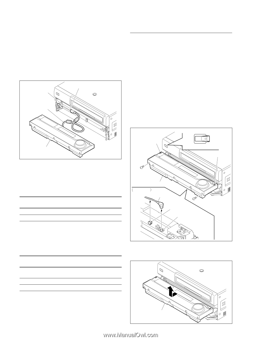
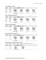
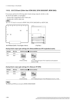
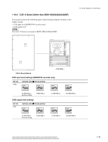
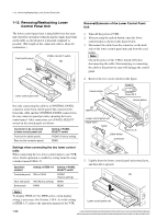
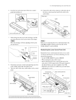
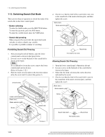
1-12. Removing/Reattaching Lower Control Panel Unit 1-12. Removing/Reattaching Lower Control Panel Unit The lower control panel unit is detachable from the main unit, therefore operation with placing the single panel unit on the table as a keyboard of a personal computer is possible. (The length of the connected cable is about 62 centimeters.) Front switch panel PANEL SELECT switch Cable Lower control panel unit Not only connecting the cable to a CONTROL PANEL connector in the front switch panel, but connection between the cable and the CONTROL PANEL connector in the rear connector panel provides operating the lower control panel. After connection, set a PANEL SELECT switch on the switch panel as follows: Connector to be connected to lower control panel unit Front (on the switch panel) Rear (on the connector panel) Setting of PANEL SELECT switch FRONT (Factory setting) REAR Settings when connecting the two lower control units When connecting the two lower control units to one VTR, select which operation to enable by setting from the setup extended menu ITEM-117. Operation enabled Setting of ITEM-117 Setting of PANEL SELECT switch Front-side panel SW or PARA FRONT (Factory setting) Rear-side panel Both panels SW (Factory setting) PARA REAR REAR n To display ITEM-117 for MSW-series, menu display setting is necessary. See Section 1-10-4. As to the setting of ITEM-117, refer to the operation manual of the VTR. Removal/Extension of the Lower Control Panel Unit 1. Turn off the power of VTR. 2. After pressing the unlock button, open the lower control panel as shown in the figure below. 3. Disconnect the cable from the connector on the back side of the lower control panel unit and from the cord holder. n Check the power of the VTR is turned off before disconnecting the cable. Disconnecting or connecting the cable in the power-on state will damage the control panel. 4. Remove the two screws shown in the figure. Unlock button POWER O I Power OFF Unlock button BVTT3 x 6 Lower control panel unit Back view Cable BVTT3 x 6 Cable holder Connector 5. Lightly draw the lower control panel unit toward you, and then lift it upward. Lower control panel unit 1-22 HDW-2000/M2000/M2000P/S2000/S2000P/M2100/M2100P, DVW-2000/2000P/M2000/M2000P MSW-2000/A2000/A2000P/M2000/M2000P/M2000E/M2000EP/M2100/M2100P/M2100E/M2100EP
-
 1
1 -
2
-
3
-
4
-
5
-
6
-
7
-
8
-
9
-
10
-
11
-
12
-
13
-
14
-
15
-
16
-
17
-
18
-
19
-
20
-
21
-
22
-
 23
23 -
 24
24 -
 25
25 -
 26
26 -
 27
27 -
 28
28 -
 29
29 -
 30
30 -
 31
31 -
 32
32 -
 33
33 -
34
-
35
-
36
-
37
-
38
-
39
-
40
-
41
-
42
-
43
-
44
-
45
-
46
-
47
-
48
 |
 |