Sony DVWM2000 Product Manual (dvwm2000 installation manual) - Page 31
Reference System
 |
View all Sony DVWM2000 manuals
Add to My Manuals
Save this manual to your list of manuals |
Page 31 highlights
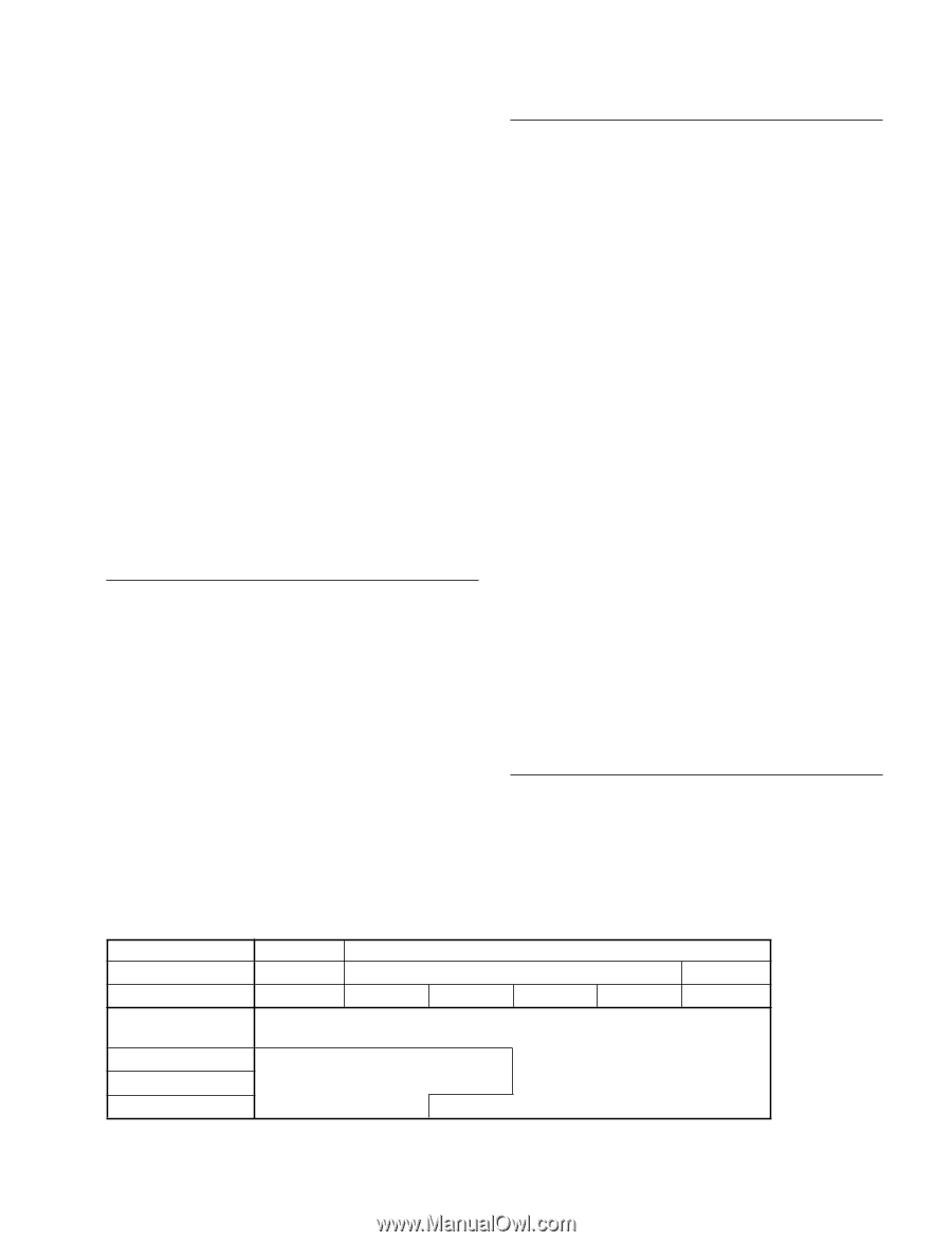
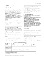
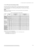
1-14. Reference System 1-14. Reference System 1-14-1. Recorder For each reference signal of the recorder, either of an external reference video signal (*3) or input video signal (*4) is automatically selected according to the setting of function menu item OUT REF, the setting of setup menu ITEM-309, and the operation mode (PB/EDIT/REC) of this unit. (Refer to the table 1-14-1 below.) In case of DVW series and MSW series, the reference signal (clock) of an analog video signal in an A/D converter regards the analog video signal itself as a reference signal under any setting. m . To select the video input, open the HOME page on the function screen and use the F1 button (VID. IN). . To set the OUT REF, open the P4 page (MISCELLA- NEOUS) on the function screen and use the F2 button (OUTREF). Audio Signal Independent Recording Even if an input video signal is selected as the reference signal, the reference signal is automatically selected to an external reference video signal for the period in which the no input video signal is input. When no external reference video signal is input, the internal-generated reference signal is automatically selected for the period. An audio signal can be independently recorded by this system even if no reference video signal is input from the outside. n In the case of DVW series and MSW series, when the setup menu ITEM-185 (AUDIO SAMPLING RATE CONVERTER) set to "44 kHz" or "32 kHz", an audio signal can be independently recorded. Alarm Display for Video Input Signal and Reference Signal 1. Blink of the selected input video indication area of the video input selection This area at the HOME page on the function screen blinks when signal is not input to the connector selected by the video input selection. 2. Blink of the STOP button The button blinks when the reference signal is not locked to an input video signal. (This function can be canceled in the setup menu ITEM-105.) . When the OUT REF is set to "INPUT": The STOP button blinks when the signal is not input to the connector selected by the video input selection. . When the OUT REF is set to "REF": The STOP button blinks in the following either cases. When no reference signal is input to REF. VIDEO connector. When the reference video signal (REF.VIDEO input) is not synchronized with an input video signal selected by the video input selection. 1-14-2. Player The player regards the external reference video signal as a reference signal. However, when no external reference video signal (REF./REF. VIDEO INPUT) is input, the player automatically switches to the reference signal generated inside the unit. Alarm Display for Reference Signal Blink of the STOP button The STOP button blinks when the signal is not input to the REF./REF. VIDEO INPUT connector. (This function can be canceled in the setup menu ITEM-105.) Table 1-14-1. Reference System for Recorder Menu ITEM-309 EXT AUTO OUT REF ----- REF Operation mode ----- PB EDIT (*1) EDIT (*2) REC Video input A/D (DVW/MSW series only) Video output process Digital audio External Reference Video (*3) Input Video (*4) Servo system *1: When the setup menu ITEM-309 is set to "AUTO1". *2: When the setup menu ITEM-309 is set to "AUTO2". *3: REF. VIDEO input *4: The input video signal is selected by the video input selection. HDW-2000/M2000/M2000P/S2000/S2000P/M2100/M2100P, DVW-2000/2000P/M2000/M2000P MSW-2000/A2000/A2000P/M2000/M2000P/M2000E/M2000EP/M2100/M2100P/M2100E/M2100EP INPUT ----- 1-25
-
 1
1 -
2
-
3
-
4
-
5
-
6
-
7
-
8
-
9
-
10
-
11
-
12
-
13
-
14
-
15
-
16
-
17
-
18
-
19
-
20
-
21
-
22
-
23
-
24
-
25
-
 26
26 -
 27
27 -
 28
28 -
 29
29 -
 30
30 -
 31
31 -
 32
32 -
 33
33 -
 34
34 -
 35
35 -
 36
36 -
37
-
38
-
39
-
40
-
41
-
42
-
43
-
44
-
45
-
46
-
47
-
48
 |
 |