Sony GV-HD700/1 Operating Guide - Page 27
In/out Rec, Hdv/dv Sel], Auto] P. 56, Component], 1080i/480i], Gv-hd700/1, Gv-hd700e/1 P. 57, Tv Type] - gv hd700e manual
 |
View all Sony GV-HD700/1 manuals
Add to My Manuals
Save this manual to your list of manuals |
Page 27 highlights
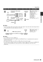
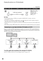
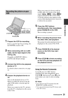
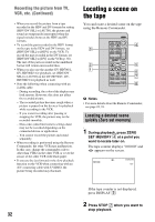
Basic Operations Type VCR Cable : Signal flow TV Menu Setting Component video cable (supplied) (Green) Y (Blue) PB/CB (Red) PR/CR A/V connecting cable (supplied) (White) (Red) (IN/OUT REC) t [HDV/DV SEL] t [AUTO] (p. 56) [COMPONENT] t [1080i/480i] (GV-HD700/1)/ [1080i/576i] (GV-HD700E/1) (p. 57) [TV TYPE] t [16:9]/[4:3] (p. 57) (Yellow) b Notes • An A/V connecting cable is also needed to output audio signals. Connect the white and red plugs of the A/ V connecting cable to the audio input jack of your TV. i.LINK cable (optional) (IN/OUT REC) t [HDV/DV SEL] t [AUTO] (p. 56) [i.LINK CONV] t [ON] (p. 57) b Notes • The TV needs to be set so that it recognizes that the VCR is connected. See the instruction manual supplied with your TV. • The VCR has a 4-pin i.LINK terminal. Select a cable that fits the terminal on the device to be connected. A/V connecting cable with S VIDEO (optional) (Yellow) (White) (Red) (IN/OUT REC) t [HDV/DV SEL] t [AUTO] (p. 56) [TV TYPE] t [16:9]/[4:3] (p. 57) b Notes • When the S VIDEO plug (S VIDEO channel) is connected, audio signals are not output. To output audio signals, connect the white and red plugs of an A/V connecting cable with S VIDEO to the audio input jack of your TV. • This connection produces higher resolution pictures compared with the A/V connecting cable (Type ). Continued , 27
-
 1
1 -
2
-
3
-
4
-
5
-
6
-
7
-
8
-
9
-
10
-
11
-
12
-
13
-
14
-
15
-
16
-
17
-
18
-
19
-
20
-
21
-
 22
22 -
 23
23 -
 24
24 -
 25
25 -
 26
26 -
 27
27 -
 28
28 -
 29
29 -
 30
30 -
 31
31 -
 32
32 -
33
-
34
-
35
-
36
-
37
-
38
-
39
-
40
-
41
-
42
-
43
-
44
-
45
-
46
-
47
-
48
-
49
-
50
-
51
-
52
-
53
-
54
-
55
-
56
-
57
-
58
-
59
-
60
-
61
-
62
-
63
-
64
-
65
-
66
-
67
-
68
-
69
-
70
-
71
-
72
-
73
-
74
-
75
-
76
-
77
-
78
-
79
-
80
-
81
-
82
-
83
-
84
-
85
-
86
-
87
-
88
-
89
-
90
-
91
-
92
-
93
-
94
-
95
-
96
-
97
-
98
-
99
-
100
-
101
-
102
-
103
-
104
-
105
-
106
-
107
-
108
-
109
-
110
-
111
-
112
 |
 |
