Sony GV-HD700/1 Operating Guide - Page 28
If your TV/VCR has a 21-pin adaptor EUROCONNECTOR GV-HD700E/1 only - digital
 |
View all Sony GV-HD700/1 manuals
Add to My Manuals
Save this manual to your list of manuals |
Page 28 highlights
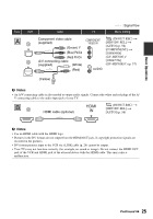
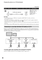
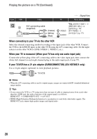
Playing the picture on a TV (Continued) Type VCR Cable TV A/V connecting cable (supplied) (Yellow) (White) (Red) : Signal flow Menu Setting (IN/OUT REC) t [HDV/DV SEL] t [AUTO] (p. 56) [TV TYPE] t [16:9]/[4:3] (p. 57) When connecting to your TV via the other VCR Select the desired connecting method according to the input jack of the other VCR. Connect the VCR to the LINE IN input on the other VCR using the A/V connecting cable. Set the input selector on the other VCR to LINE (VIDEO 1, VIDEO 2, etc.). When your TV is monaural (When your TV has only one audio input jack) Connect the yellow plug of the A/V connecting cable to the video input jack, then connect the white (left channel) or red (right channel) plug to the audio input jack of your TV. If your TV/VCR has a 21-pin adaptor (EUROCONNECTOR) (GV-HD700E/1 only) Use a 21-pin adaptor (optional) to view playback pictures. b Notes • When the A/V connecting cable is used to output images, images are output with SD (standard definition) image quality. z Tips • If you connect the VCR to a TV using more than one type of cable to output pictures from a jack other than the i.LINK jack, the order of priority of the output signal is as follows: HDMI OUT t COMPONENT OUT t A/V OUT • HDMI (High-Definition Multimedia Interface) is an interface to send both video/audio signals. The HDMI OUT jack outputs high quality images and digital audio. 28
-
 1
1 -
2
-
3
-
4
-
5
-
6
-
7
-
8
-
9
-
10
-
11
-
12
-
13
-
14
-
15
-
16
-
17
-
18
-
19
-
20
-
21
-
22
-
 23
23 -
 24
24 -
 25
25 -
 26
26 -
 27
27 -
 28
28 -
 29
29 -
 30
30 -
 31
31 -
 32
32 -
 33
33 -
34
-
35
-
36
-
37
-
38
-
39
-
40
-
41
-
42
-
43
-
44
-
45
-
46
-
47
-
48
-
49
-
50
-
51
-
52
-
53
-
54
-
55
-
56
-
57
-
58
-
59
-
60
-
61
-
62
-
63
-
64
-
65
-
66
-
67
-
68
-
69
-
70
-
71
-
72
-
73
-
74
-
75
-
76
-
77
-
78
-
79
-
80
-
81
-
82
-
83
-
84
-
85
-
86
-
87
-
88
-
89
-
90
-
91
-
92
-
93
-
94
-
95
-
96
-
97
-
98
-
99
-
100
-
101
-
102
-
103
-
104
-
105
-
106
-
107
-
108
-
109
-
110
-
111
-
112
 |
 |
