Toshiba TLP-MT7 Owner's Manual - English - Page 10
Names of each part on the main unit
 |
UPC - 022265950821
View all Toshiba TLP-MT7 manuals
Add to My Manuals
Save this manual to your list of manuals |
Page 10 highlights
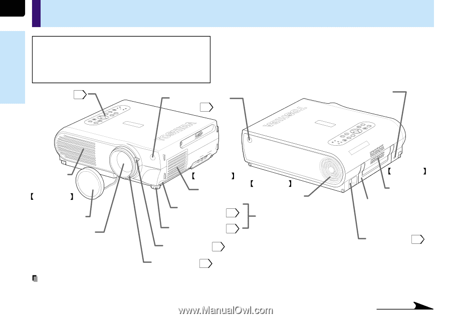
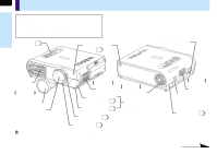
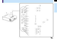
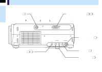
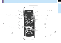
10 Names of each part on the main unit Before use CAUTION Openings in the cabinet are provided for ventilation and to ensure reliable operation of the product and to protect it from overheating, and these openings must not be blocked or covered. Control panel 11 LAMP FAN TEMP BUSY Infrared remote sensor 15 Anti-theft lock hole MENU INPUT ON/STANDBY ON EXIT ENTER KEYSATUOTNOE VOL/ADJ. SAEUTTO Air exhaust Front side Lens cover Lens CONTROL C(OCMOPMOPNUETNETRI)N AUINDIO VIDEOVIIDNEO S-VIDEO R - AUDIO - L Right side Air intake Foot adjuster release button 19 Foot adjuster 19 Zooming lever 27 ENTER MENU INPUT TEMP BUSY LAMP FAN ON/STANDBY ON EXIT KEYASUTOTONE VOL/ADJ. SAEUTTO Rear side Air intake Also mounted on the front of the left side. Left side Speaker Carrying handle Open to carry the projector. AC IN socket 18 Focusing ring 27 Note The air exhaust discharges high temperature air. Do not put something around the air exhaust, otherwise it may be deformed by the high temperature air. Continued
-
 1
1 -
2
-
3
-
4
-
 5
5 -
 6
6 -
 7
7 -
 8
8 -
 9
9 -
 10
10 -
 11
11 -
 12
12 -
 13
13 -
 14
14 -
 15
15 -
16
-
17
-
18
-
19
-
20
-
21
-
22
-
23
-
24
-
25
-
26
-
27
-
28
-
29
-
30
-
31
-
32
-
33
-
34
-
35
-
36
-
37
-
38
-
39
-
40
-
41
-
42
-
43
-
44
-
45
-
46
-
47
-
48
-
49
-
50
-
51
-
52
-
53
-
54
-
55
-
56
-
57
-
58
-
59
-
60
-
61
-
62
-
63
-
64
-
65
-
66
-
67
-
68
-
69
-
70
-
71
-
72
-
73
-
74
-
75
-
76
-
77
-
78
-
79
-
80
 |
 |