Toshiba U100 PLU10C Users Manual Canada; English - Page 108
Attaching the ferrite core to the modular cable, Free the lock and the ferrite core is opened.
 |
View all Toshiba U100 PLU10C manuals
Add to My Manuals
Save this manual to your list of manuals |
Page 108 highlights
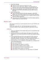
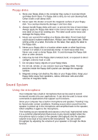
Operating Basics Attaching the ferrite core to the modular cable The ferrite core that attaches to the modular cable bundled with this product is explained here. When connecting the modular cable, attaching the bundled ferrite core to the modular cable will help to reduce noise. To attach the ferrite core, follow the steps below. When attaching the ferrite core to the modular cable, please ensure that the cable is set in the dimpled portion of the ferrite core. Furthermore, please set the connector that is used to connect to the computer outside the ferrite core. The modular cable might be damaged if the cable is not set within the dimpled portion or the connector is set within the ferrite core. 1. Free the lock and the ferrite core is opened. Lock Figure 4-10 Opening the ferrite core 2. Adjust the modular cable so that it falls in the center dimple of the ferrite core. Please ensure that the connector of modular cable and the ferrite core are placed around 30mm apart. Ferrite core Figure 4-11 Opening the ferrite core 4-30 User's Manual
-
 1
1 -
2
-
3
-
4
-
5
-
6
-
7
-
8
-
9
-
10
-
11
-
12
-
13
-
14
-
15
-
16
-
17
-
18
-
19
-
20
-
21
-
22
-
23
-
24
-
25
-
26
-
27
-
28
-
29
-
30
-
31
-
32
-
33
-
34
-
35
-
36
-
37
-
38
-
39
-
40
-
41
-
42
-
43
-
44
-
45
-
46
-
47
-
48
-
49
-
50
-
51
-
52
-
53
-
54
-
55
-
56
-
57
-
58
-
59
-
60
-
61
-
62
-
63
-
64
-
65
-
66
-
67
-
68
-
69
-
70
-
71
-
72
-
73
-
74
-
75
-
76
-
77
-
78
-
79
-
80
-
81
-
82
-
83
-
84
-
85
-
86
-
87
-
88
-
89
-
90
-
91
-
92
-
93
-
94
-
95
-
96
-
97
-
98
-
99
-
100
-
101
-
102
-
 103
103 -
 104
104 -
 105
105 -
 106
106 -
 107
107 -
 108
108 -
 109
109 -
 110
110 -
 111
111 -
 112
112 -
 113
113 -
114
-
115
-
116
-
117
-
118
-
119
-
120
-
121
-
122
-
123
-
124
-
125
-
126
-
127
-
128
-
129
-
130
-
131
-
132
-
133
-
134
-
135
-
136
-
137
-
138
-
139
-
140
-
141
-
142
-
143
-
144
-
145
-
146
-
147
-
148
-
149
-
150
-
151
-
152
-
153
-
154
-
155
-
156
-
157
-
158
-
159
-
160
-
161
-
162
-
163
-
164
-
165
-
166
-
167
-
168
-
169
-
170
-
171
-
172
-
173
-
174
-
175
-
176
-
177
-
178
-
179
-
180
-
181
-
182
-
183
-
184
-
185
-
186
-
187
-
188
-
189
-
190
-
191
-
192
-
193
-
194
-
195
-
196
-
197
-
198
-
199
-
200
-
201
-
202
-
203
-
204
-
205
-
206
-
207
-
208
-
209
-
210
-
211
-
212
-
213
-
214
-
215
-
216
-
217
-
218
-
219
-
220
-
221
-
222
-
223
-
224
-
225
-
226
-
227
-
228
-
229
-
230
-
231
-
232
-
233
-
234
-
235
-
236
-
237
-
238
-
239
-
240
-
241
-
242
-
243
-
244
-
245
-
246
-
247
-
248
-
249
-
250
-
251
-
252
-
253
-
254
 |
 |
