Weider Pro 9020 English Manual - Page 40
Cable Diagrams
 |
View all Weider Pro 9020 manuals
Add to My Manuals
Save this manual to your list of manuals |
Page 40 highlights
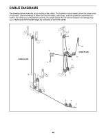
CABLE DIAGRAMS The drawings below shows the proper routing of the cables. The numbers in each drawing show the proper route of that cable. Use the drawings to make sure that the cables, cable traps, and half guards are assembled correctly. If the cables are not assembled correctly, the weight system will not function properly and damage may occur. Make sure that the cable traps do not touch or bind the cables. 7 2 Cable A (63) 1 8 5 6 4 6 48 10 Cable B (64) 9 3 7 5 3 2 1 40
-
 1
1 -
2
-
3
-
4
-
5
-
6
-
7
-
8
-
9
-
10
-
11
-
12
-
13
-
14
-
15
-
16
-
17
-
18
-
19
-
20
-
21
-
22
-
23
-
24
-
25
-
26
-
27
-
28
-
29
-
30
-
31
-
32
-
33
-
34
-
 35
35 -
 36
36 -
 37
37 -
 38
38 -
 39
39 -
 40
40 -
 41
41 -
 42
42 -
 43
43 -
 44
44 -
 45
45 -
46
-
47
-
48
-
49
-
50
-
51
-
52
 |
 |

40
The drawings below shows the proper routing of the cables. The numbers in each drawing show the proper route
of that cable. Use the drawings to make sure that the cables, cable traps, and half guards are assembled cor-
rectly. If the cables are not assembled correctly, the weight system will not function properly and damage may
occur.
Make sure that the cable traps do not touch or bind the cables.
CABLE DIAGRAMS
7
8
5
6
4
3
2
1
1
2
3
4
7
5
8
9
6
10
Cable A (63)
Cable B (64)