Xerox 2135N Quick Reference Guide - Page 12
Service Guide
 |
UPC - 042215474689
View all Xerox 2135N manuals
Add to My Manuals
Save this manual to your list of manuals |
Page 12 highlights
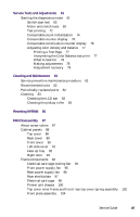
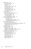
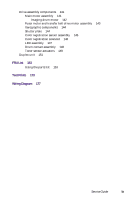
Removing the tray 1 entrance sensor actuator 121 Removing the belt entrance sensor actuator 122 Removing the duplex solenoid and the exit solenoid 123 Removing the transfer belt unit 124 Removing the registration clutch 125 Removing the registration motor assembly 126 Removing the registration roller assembly A and drive gear 128 Removing the registration roller assembly B 129 Removing the duplex guide assembly 131 Fuser latching handle (left) 133 Fuser latching handle (left) 134 Removing the fuser exit roller 136 Removing the exit sensor assembly 137 Removing the eject guide assembly 138 Removing the stack full sensor 140 Removing the main motor assembly 142 Removing the fuser motor and transfer belt drive motor assembly 143 Removing the shutter plate 144 Removing the color registration sensor assembly 145 Removing the color registration solenoid 146 Removing an LED assembly 147 Removing the drum contact assembly 148 Removing the toner sensor actuators 150 Removing the duplex unit 151 Cabinet and top cover FRUs 155 Top cover FRUs 157 Printer chassis FRUs (1 of 2) 159 Printer chassis FRUs (2 of 2) 161 Paper tray and paper tray guides FRUs 163 Electrical components FRUs 164 Duplexer unit 165 Lower Tray Assembly FRUs 167 Wiring diagram 177 Wire routing at the engine controller board 178 Details of wiring passthru 179 Wiring under the top shield plate 180 Wiring harnesses route by the imaging drum motors 181 Wire routing by the fuser and transfer belt motor unit. 181 Ribbon cable routing under the toner sensor board 182 Service Guide xi
-
 1
1 -
2
-
3
-
4
-
5
-
6
-
 7
7 -
 8
8 -
 9
9 -
 10
10 -
 11
11 -
 12
12 -
 13
13 -
 14
14 -
 15
15 -
 16
16 -
 17
17 -
18
-
19
-
20
-
21
-
22
-
23
-
24
-
25
-
26
-
27
-
28
-
29
-
30
-
31
-
32
-
33
-
34
-
35
-
36
-
37
-
38
-
39
-
40
-
41
-
42
-
43
-
44
-
45
-
46
-
47
-
48
-
49
-
50
-
51
-
52
-
53
-
54
-
55
-
56
-
57
-
58
-
59
-
60
-
61
-
62
-
63
-
64
-
65
-
66
-
67
-
68
-
69
-
70
-
71
-
72
-
73
-
74
-
75
-
76
-
77
-
78
-
79
-
80
-
81
-
82
-
83
-
84
-
85
-
86
-
87
-
88
-
89
-
90
-
91
-
92
-
93
-
94
-
95
-
96
-
97
-
98
-
99
-
100
-
101
-
102
-
103
-
104
-
105
-
106
-
107
-
108
-
109
-
110
-
111
-
112
-
113
-
114
-
115
-
116
-
117
-
118
-
119
-
120
-
121
-
122
-
123
-
124
-
125
-
126
-
127
-
128
-
129
-
130
-
131
-
132
-
133
-
134
-
135
-
136
-
137
-
138
-
139
-
140
-
141
-
142
-
143
-
144
-
145
-
146
-
147
-
148
-
149
-
150
-
151
-
152
-
153
-
154
-
155
-
156
-
157
-
158
-
159
-
160
-
161
-
162
-
163
-
164
-
165
-
166
-
167
-
168
-
169
-
170
-
171
-
172
-
173
-
174
-
175
-
176
-
177
-
178
-
179
-
180
-
181
-
182
-
183
-
184
-
185
-
186
-
187
-
188
-
189
-
190
-
191
-
192
-
193
-
194
-
195
-
196
-
197
-
198
-
199
 |
 |
