Xerox 2135N Quick Reference Guide - Page 81
L - Opened
 |
UPC - 042215474689
View all Xerox 2135N manuals
Add to My Manuals
Save this manual to your list of manuals |
Page 81 highlights
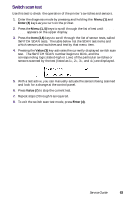
Switch scans and the sensor and switches test Switch or sensor Switch scan test Tray 5, Size 1 Switch Scan 21 Switch - (Top) 1= Tray 5, Size 2 Switch Scan 21 Switch 2= Tray 5, Size 3 Switch Scan 21 Switch 3= Tray 5, Size 4 Switch Scan 21 Switch - (Bottom) 4= Tray 5 No Paper Switch Scan 22 Sensor 1= Tray 5 Low Paper Switch Scan 22 Sensor 2= not used Switch Scan 22 3= not used Switch Scan 22 4= Right Door Tray 5 Switch Scan 23 1= not used Switch Scan 23 2= not used Switch Scan 23 3= not used Switch Scan 23 4= Black LED Head Switch Scan 24 temperature 1= Yellow LED Head Switch Scan 24 temperature 2= Magenta LED Switch Scan 24 Head temperature 3= Cyan LED Head Switch Scan 24 temperature 4= Black Imaging Switch Scan 25 Drum Contact 1= Cyan Imaging Switch Scan 25 Drum Contact 2= Magenta Imaging Switch Scan 25 Drum Contact 3= Yellow Imaging Switch Scan 25 Drum Contact 4= Test result L - Actuated H - Deactuated L - Actuated H - Deactuated L - Actuated H - Deactuated L - Actuated H - Deactuated L - Paper present H - No paper L - Paper level OK H - Low paper not used Details Remove the tray and actuate the sensor flags at the rear of the tray cavity Pull tray out to test sensor Pull tray out to test sensor not used L - Opened H - Closed not used Open door to test sensor not used not used Encoded head temperature Encoded head temperature Encoded head temperature Encoded head temperature L - Installed H - Missing L - Installed H - Missing L - Installed H - Missing L - Installed H - Missing Temperature is encoded as a hexidecimal value. The default is between 083 and 316. Tests the imaging drum up/down sensor. Remove drum unit to test. 68 Phaser 2135 Color Printer
-
 1
1 -
2
-
3
-
4
-
5
-
6
-
7
-
8
-
9
-
10
-
11
-
12
-
13
-
14
-
15
-
16
-
17
-
18
-
19
-
20
-
21
-
22
-
23
-
24
-
25
-
26
-
27
-
28
-
29
-
30
-
31
-
32
-
33
-
34
-
35
-
36
-
37
-
38
-
39
-
40
-
41
-
42
-
43
-
44
-
45
-
46
-
47
-
48
-
49
-
50
-
51
-
52
-
53
-
54
-
55
-
56
-
57
-
58
-
59
-
60
-
61
-
62
-
63
-
64
-
65
-
66
-
67
-
68
-
69
-
70
-
71
-
72
-
73
-
74
-
75
-
 76
76 -
 77
77 -
 78
78 -
 79
79 -
 80
80 -
 81
81 -
 82
82 -
 83
83 -
 84
84 -
 85
85 -
 86
86 -
87
-
88
-
89
-
90
-
91
-
92
-
93
-
94
-
95
-
96
-
97
-
98
-
99
-
100
-
101
-
102
-
103
-
104
-
105
-
106
-
107
-
108
-
109
-
110
-
111
-
112
-
113
-
114
-
115
-
116
-
117
-
118
-
119
-
120
-
121
-
122
-
123
-
124
-
125
-
126
-
127
-
128
-
129
-
130
-
131
-
132
-
133
-
134
-
135
-
136
-
137
-
138
-
139
-
140
-
141
-
142
-
143
-
144
-
145
-
146
-
147
-
148
-
149
-
150
-
151
-
152
-
153
-
154
-
155
-
156
-
157
-
158
-
159
-
160
-
161
-
162
-
163
-
164
-
165
-
166
-
167
-
168
-
169
-
170
-
171
-
172
-
173
-
174
-
175
-
176
-
177
-
178
-
179
-
180
-
181
-
182
-
183
-
184
-
185
-
186
-
187
-
188
-
189
-
190
-
191
-
192
-
193
-
194
-
195
-
196
-
197
-
198
-
199
 |
 |
