Xerox 2135N Quick Reference Guide - Page 62
Blank print
 |
UPC - 042215474689
View all Xerox 2135N manuals
Add to My Manuals
Save this manual to your list of manuals |
Page 62 highlights
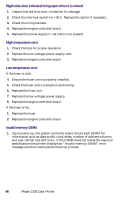
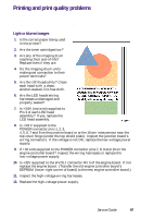
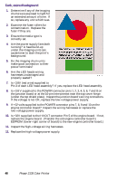
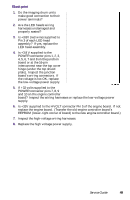
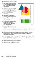
Blank print 1. Do the imaging drum units make good connection to their power terminals? 2. Are the LED heads wiring harnesses undamaged and properly seated? 3. Is +3.8V (red wire) supplied to Pin 3 of each LED head assembly? If yes, replace the LED head assembly. 4. Is +3.8 V supplied to the POWER connector pins 1, 2, 3, 4, 5, 6, 7 and 8 on the junction board or at the 16-pin interconnect near the top cover hinge (under the top shield plate). Inspect the junction board's wiring connectors. If the voltage is not OK, replace the low-voltage power supply. 5. If +32 volts supplied to the POWER connector pins 7, 8, 9 and 10 on the engine controller board? Inspect the wiring harnesses or replace the low-voltage power supply. 6. Is +32V supplied to the HVOLT connector Pin 5 of the engine board. If not, replace the engine board. (Transfer the old engine controller board's EEPROM (lower-right corner of board) to the new engine controller board.) 7. Inspect the high-voltage wiring harnesses. 8. Replace the high voltage power supply. Service Guide 49
-
 1
1 -
2
-
3
-
4
-
5
-
6
-
7
-
8
-
9
-
10
-
11
-
12
-
13
-
14
-
15
-
16
-
17
-
18
-
19
-
20
-
21
-
22
-
23
-
24
-
25
-
26
-
27
-
28
-
29
-
30
-
31
-
32
-
33
-
34
-
35
-
36
-
37
-
38
-
39
-
40
-
41
-
42
-
43
-
44
-
45
-
46
-
47
-
48
-
49
-
50
-
51
-
52
-
53
-
54
-
55
-
56
-
 57
57 -
 58
58 -
 59
59 -
 60
60 -
 61
61 -
 62
62 -
 63
63 -
 64
64 -
 65
65 -
 66
66 -
 67
67 -
68
-
69
-
70
-
71
-
72
-
73
-
74
-
75
-
76
-
77
-
78
-
79
-
80
-
81
-
82
-
83
-
84
-
85
-
86
-
87
-
88
-
89
-
90
-
91
-
92
-
93
-
94
-
95
-
96
-
97
-
98
-
99
-
100
-
101
-
102
-
103
-
104
-
105
-
106
-
107
-
108
-
109
-
110
-
111
-
112
-
113
-
114
-
115
-
116
-
117
-
118
-
119
-
120
-
121
-
122
-
123
-
124
-
125
-
126
-
127
-
128
-
129
-
130
-
131
-
132
-
133
-
134
-
135
-
136
-
137
-
138
-
139
-
140
-
141
-
142
-
143
-
144
-
145
-
146
-
147
-
148
-
149
-
150
-
151
-
152
-
153
-
154
-
155
-
156
-
157
-
158
-
159
-
160
-
161
-
162
-
163
-
164
-
165
-
166
-
167
-
168
-
169
-
170
-
171
-
172
-
173
-
174
-
175
-
176
-
177
-
178
-
179
-
180
-
181
-
182
-
183
-
184
-
185
-
186
-
187
-
188
-
189
-
190
-
191
-
192
-
193
-
194
-
195
-
196
-
197
-
198
-
199
 |
 |
