Xerox 2135N Quick Reference Guide - Page 48
Ensuring the +5 VDC loop is complete
 |
UPC - 042215474689
View all Xerox 2135N manuals
Add to My Manuals
Save this manual to your list of manuals |
Page 48 highlights
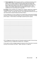
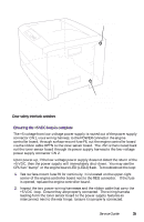
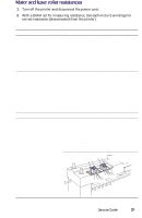
Top Cover Open Switch Door safety interlock switches Front Cover Open Switch 0725-63 Ensuring the +5 VDC loop is complete The +5 voltage from low-voltage power supply is routed out of the power supply connector CN1, via a wiring harness, to the POWER connector the engine controller board, through surface-mount fuse F6, out the engine controller board via the ribbon cable OPTN to the toner sensor board. The +5V is then routed back out the toner sensor board through its power supply harness to the low-voltage power supply connector CN 2. Upon power-up, if the low-voltage power supply does not detect the return of the +5 VDC, then the power supply will immediately shut-down. You may see the CPU fan "bump" or the engine board LED (LED2) flash. To troubleshoot the loop: 1. Test surface-mount fuse F6 for continuity. It is located on the upper-right corner of the engine controller board next to the REG connector. If the fuse is opened, replace the engine controller board. 2. Inspect the two power wiring harnesses and the ribbon cable that carry the +5 VDC loop. Ensure they are properly connected. The wiring harness leading form the toner sensor board to the power supply features an interconnect next to the rear hinge. Ensure it is properly connected. Service Guide 35
-
 1
1 -
2
-
3
-
4
-
5
-
6
-
7
-
8
-
9
-
10
-
11
-
12
-
13
-
14
-
15
-
16
-
17
-
18
-
19
-
20
-
21
-
22
-
23
-
24
-
25
-
26
-
27
-
28
-
29
-
30
-
31
-
32
-
33
-
34
-
35
-
36
-
37
-
38
-
39
-
40
-
41
-
42
-
 43
43 -
 44
44 -
 45
45 -
 46
46 -
 47
47 -
 48
48 -
 49
49 -
 50
50 -
 51
51 -
 52
52 -
 53
53 -
54
-
55
-
56
-
57
-
58
-
59
-
60
-
61
-
62
-
63
-
64
-
65
-
66
-
67
-
68
-
69
-
70
-
71
-
72
-
73
-
74
-
75
-
76
-
77
-
78
-
79
-
80
-
81
-
82
-
83
-
84
-
85
-
86
-
87
-
88
-
89
-
90
-
91
-
92
-
93
-
94
-
95
-
96
-
97
-
98
-
99
-
100
-
101
-
102
-
103
-
104
-
105
-
106
-
107
-
108
-
109
-
110
-
111
-
112
-
113
-
114
-
115
-
116
-
117
-
118
-
119
-
120
-
121
-
122
-
123
-
124
-
125
-
126
-
127
-
128
-
129
-
130
-
131
-
132
-
133
-
134
-
135
-
136
-
137
-
138
-
139
-
140
-
141
-
142
-
143
-
144
-
145
-
146
-
147
-
148
-
149
-
150
-
151
-
152
-
153
-
154
-
155
-
156
-
157
-
158
-
159
-
160
-
161
-
162
-
163
-
164
-
165
-
166
-
167
-
168
-
169
-
170
-
171
-
172
-
173
-
174
-
175
-
176
-
177
-
178
-
179
-
180
-
181
-
182
-
183
-
184
-
185
-
186
-
187
-
188
-
189
-
190
-
191
-
192
-
193
-
194
-
195
-
196
-
197
-
198
-
199
 |
 |
