Xerox 2135N Quick Reference Guide - Page 50
Motor and fuser roller resistances
 |
UPC - 042215474689
View all Xerox 2135N manuals
Add to My Manuals
Save this manual to your list of manuals |
Page 50 highlights
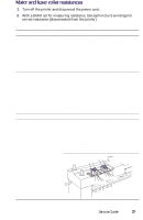
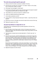
Motor and fuser roller resistances 1. Turn off the printer and disconnect the power cord. 2. With a DMM set for measuring resistance, test each motor's windings for correct resistance (disconnected from the printer). Motor and fuser roller resistances Motor Measure between ... Resistance Yellow drum unit motor Magenta drum unit motor Cyan drum unit motor Black drum unit motor Between motor Pins 1 and 2 Between motor Pins 3 and 4 ~3 Ω ~3 Ω All the drum motors connect to connector ID at the top of the engine controller board Black Pins 1 thru 4 Yellow Pins 5 thru 8 magenta Pins 9 thru 12 Cyan Pins 13 thru 16 Transfer belt motor Registration motor Fuser motor Main feed drive motor Between motor Pins 1 and 2 Between motor Pins 3 and 4 The transfer belt motor connects to connector BELTHET pins 5 thru 8 ~8 Ω ~8 Ω The feed motor connects to connector HOPFF pins 1 thru 4 The main motor connects to connector HOPFF pins 5 thru 8 Tray lift motor Between motor Pins 1 and 2 ~100 Ω Fuser unit New fuser: The resistance between pins C and D of the lower roller will be O Ω, a fuse. Used fuser: The fuse between pins C and D of the lower roller will be open. The fuse indicates a new fuser and is blown within seconds of being installed to indicate a fuser now in use. Upper Roller Between Pins A and B Between Pins C and D Between Pins E and F Lower Roller Between Pins A and B Between Pins C and D Between Pins E and F B A B A 2 Ω Open ~360 at 25oC 3 Ω 0 Ω or open (fuse) ~360 at 25oC C D E F C D E F Underside of fuser 0728-02 Service Guide 37
-
 1
1 -
2
-
3
-
4
-
5
-
6
-
7
-
8
-
9
-
10
-
11
-
12
-
13
-
14
-
15
-
16
-
17
-
18
-
19
-
20
-
21
-
22
-
23
-
24
-
25
-
26
-
27
-
28
-
29
-
30
-
31
-
32
-
33
-
34
-
35
-
36
-
37
-
38
-
39
-
40
-
41
-
42
-
43
-
44
-
 45
45 -
 46
46 -
 47
47 -
 48
48 -
 49
49 -
 50
50 -
 51
51 -
 52
52 -
 53
53 -
 54
54 -
 55
55 -
56
-
57
-
58
-
59
-
60
-
61
-
62
-
63
-
64
-
65
-
66
-
67
-
68
-
69
-
70
-
71
-
72
-
73
-
74
-
75
-
76
-
77
-
78
-
79
-
80
-
81
-
82
-
83
-
84
-
85
-
86
-
87
-
88
-
89
-
90
-
91
-
92
-
93
-
94
-
95
-
96
-
97
-
98
-
99
-
100
-
101
-
102
-
103
-
104
-
105
-
106
-
107
-
108
-
109
-
110
-
111
-
112
-
113
-
114
-
115
-
116
-
117
-
118
-
119
-
120
-
121
-
122
-
123
-
124
-
125
-
126
-
127
-
128
-
129
-
130
-
131
-
132
-
133
-
134
-
135
-
136
-
137
-
138
-
139
-
140
-
141
-
142
-
143
-
144
-
145
-
146
-
147
-
148
-
149
-
150
-
151
-
152
-
153
-
154
-
155
-
156
-
157
-
158
-
159
-
160
-
161
-
162
-
163
-
164
-
165
-
166
-
167
-
168
-
169
-
170
-
171
-
172
-
173
-
174
-
175
-
176
-
177
-
178
-
179
-
180
-
181
-
182
-
183
-
184
-
185
-
186
-
187
-
188
-
189
-
190
-
191
-
192
-
193
-
194
-
195
-
196
-
197
-
198
-
199
 |
 |
