Xerox 2135N Quick Reference Guide - Page 57
Fan error, Fuser unit error - driver
 |
UPC - 042215474689
View all Xerox 2135N manuals
Add to My Manuals
Save this manual to your list of manuals |
Page 57 highlights
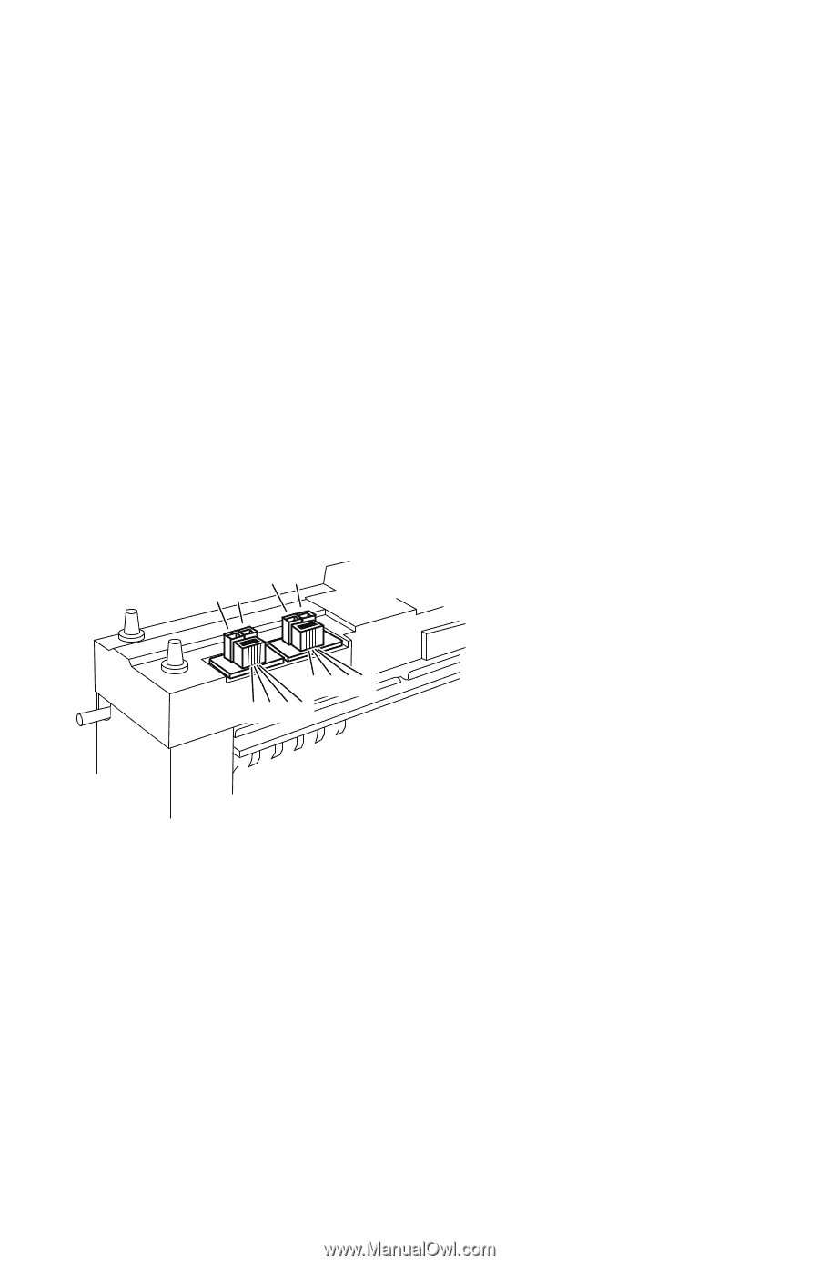
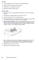
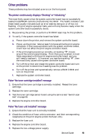
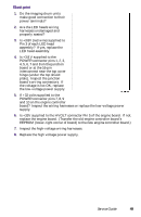
Fan error 1. Is power supplied to pin 1 of the fan? If yes, replace the fan. 2. Inspect the fan's wiring harness for damage. 3. Replace the low-voltage power supply 4. Replace the engine controller board. Fuser unit error 1. Does the error occur immediately after the printer is turned on? Replace the fuser. 2. Check that AC voltage supplied to the printer is correct. 3. Does the fuser get hot? If not, replace the fuser. 4. If the fuser does warm up, verify that it is reaching the correct temperature by running the service test "Switch scan test" on page 63. 5. If the fuser does not get warm. Does AC voltage appear between Pins 1 and 2 of CN 4-1 and CN 4-2 of the fuser connector. These pins connect to Pins A and B of the fuser (illustrated below) when the fuser is installed. Remove the fuser to check. If not, replace the power supply. B A B A C D E F C D E F Underside of fuser 0728-02 Bear in mind that the correct AC voltage may be present at Pins 1 and 2 of CN 4-1 and CN 4-2 even though the drivers ICs feeding these pins are damaged and cannot deliver the current required by the fuser heaters. 6. Replace the engine controller board. 7. Replace the low-voltage power supply. 44 Phaser 2135 Color Printer
-
 1
1 -
2
-
3
-
4
-
5
-
6
-
7
-
8
-
9
-
10
-
11
-
12
-
13
-
14
-
15
-
16
-
17
-
18
-
19
-
20
-
21
-
22
-
23
-
24
-
25
-
26
-
27
-
28
-
29
-
30
-
31
-
32
-
33
-
34
-
35
-
36
-
37
-
38
-
39
-
40
-
41
-
42
-
43
-
44
-
45
-
46
-
47
-
48
-
49
-
50
-
51
-
 52
52 -
 53
53 -
 54
54 -
 55
55 -
 56
56 -
 57
57 -
 58
58 -
 59
59 -
 60
60 -
 61
61 -
 62
62 -
63
-
64
-
65
-
66
-
67
-
68
-
69
-
70
-
71
-
72
-
73
-
74
-
75
-
76
-
77
-
78
-
79
-
80
-
81
-
82
-
83
-
84
-
85
-
86
-
87
-
88
-
89
-
90
-
91
-
92
-
93
-
94
-
95
-
96
-
97
-
98
-
99
-
100
-
101
-
102
-
103
-
104
-
105
-
106
-
107
-
108
-
109
-
110
-
111
-
112
-
113
-
114
-
115
-
116
-
117
-
118
-
119
-
120
-
121
-
122
-
123
-
124
-
125
-
126
-
127
-
128
-
129
-
130
-
131
-
132
-
133
-
134
-
135
-
136
-
137
-
138
-
139
-
140
-
141
-
142
-
143
-
144
-
145
-
146
-
147
-
148
-
149
-
150
-
151
-
152
-
153
-
154
-
155
-
156
-
157
-
158
-
159
-
160
-
161
-
162
-
163
-
164
-
165
-
166
-
167
-
168
-
169
-
170
-
171
-
172
-
173
-
174
-
175
-
176
-
177
-
178
-
179
-
180
-
181
-
182
-
183
-
184
-
185
-
186
-
187
-
188
-
189
-
190
-
191
-
192
-
193
-
194
-
195
-
196
-
197
-
198
-
199
 |
 |