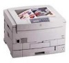
Xerox 2135N Quick Reference Guide - Page 32
Jam Inside Right Door A, Open Right Door
 |
UPC - 042215474689
View all Xerox 2135N manuals
Add to My Manuals
Save this manual to your list of manuals |
Page 32 highlights
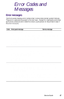
Printer fault messages Code B21 C1 C2 C3 C4 C5 E1 E2 E3 E4 E5 E9 E12 Front panel message Service message Jam Inside Right Door A, Open Right Door A B21-Duplex Area Jam 1. Ensure the correct weight and type of paper is loaded in the currently used tray. Also ensure the paper is loaded correctly in the tray. 2. Clean the duplex unit's rollers. 3. Test the duplex motor and clutch as described in "Motor and clutch tests" on page 69. 4. Replace the duplex unit. 5. Replace the engine controller board. Close Tray 1, Tray 1 Not Detected C1-Check Tray 1 Close Tray 2, Tray 2 Not Detected C2-Check Tray 2 Close Tray 3, Tray 3 Not Detected C3-Check Tray 3 Close Tray 4, Tray 4 Not Detected C3-Check Tray 4 Close Tray 5, Tray 5 Not Detected C3-Check Tray 5 1. Ensure the tray is installed correctly. 2. Inspect and test the paper size sensors and the tray's corresponding sensor flags. 3. Replace the paper tray sensor board 4. Replace the paper tray. 5. Replace the engine controller board. Tray 1 Misfeed, Open Rt Door A and Tray 1 E1-Tray 1 Misfeed Tray 2 Misfeed, Open Rt Door B and Tray 2 E1-Tray 2 Misfeed Tray 3 Misfeed, Open Rt Door C and Tray 3 E1-Tray 3 Misfeed Tray 4 Misfeed, Open Rt Door D and Tray 4 E1-Tray 4 Misfeed Tray 5 Misfeed, Open Rt Door E and Tray 5 E1-Tray 5 Misfeed 1. Ensure the correct weight and type of paper is loaded in the tray. Also ensure the paper is loaded correctly in the tray. 2. Clean the pick rollers. 3. Test the main feed motor as described in "Motor and clutch tests" on page 69. 4. Replace the main feed motor. 5. Replace the engine controller board. Top Cover Open, Close Top Cover A E9-Top Cover A Open 1. Close the cover. 2. Inspect the switch and ensure the switch's actuator is not broken. 3. Test the top cover open switch using the sensor test described in "Switch scan test" on page 63. 4. Inspect the switch's wiring harness. 5. Replace the engine controller board. Top Output Tray Full Remove Output E12-Output Bin Full, Top 1. Ensure the output bin full sensor flag operates freely. 2. Test the output bin full sensor using the test described in "Switch scan test" on page 63. 3. Inspect the sensor and its wiring harness. 4. Replace the engine controller board. Service Guide 19
-
 1
1 -
2
-
3
-
4
-
5
-
6
-
7
-
8
-
9
-
10
-
11
-
12
-
13
-
14
-
15
-
16
-
17
-
18
-
19
-
20
-
21
-
22
-
23
-
24
-
25
-
26
-
 27
27 -
 28
28 -
 29
29 -
 30
30 -
 31
31 -
 32
32 -
 33
33 -
 34
34 -
 35
35 -
 36
36 -
 37
37 -
38
-
39
-
40
-
41
-
42
-
43
-
44
-
45
-
46
-
47
-
48
-
49
-
50
-
51
-
52
-
53
-
54
-
55
-
56
-
57
-
58
-
59
-
60
-
61
-
62
-
63
-
64
-
65
-
66
-
67
-
68
-
69
-
70
-
71
-
72
-
73
-
74
-
75
-
76
-
77
-
78
-
79
-
80
-
81
-
82
-
83
-
84
-
85
-
86
-
87
-
88
-
89
-
90
-
91
-
92
-
93
-
94
-
95
-
96
-
97
-
98
-
99
-
100
-
101
-
102
-
103
-
104
-
105
-
106
-
107
-
108
-
109
-
110
-
111
-
112
-
113
-
114
-
115
-
116
-
117
-
118
-
119
-
120
-
121
-
122
-
123
-
124
-
125
-
126
-
127
-
128
-
129
-
130
-
131
-
132
-
133
-
134
-
135
-
136
-
137
-
138
-
139
-
140
-
141
-
142
-
143
-
144
-
145
-
146
-
147
-
148
-
149
-
150
-
151
-
152
-
153
-
154
-
155
-
156
-
157
-
158
-
159
-
160
-
161
-
162
-
163
-
164
-
165
-
166
-
167
-
168
-
169
-
170
-
171
-
172
-
173
-
174
-
175
-
176
-
177
-
178
-
179
-
180
-
181
-
182
-
183
-
184
-
185
-
186
-
187
-
188
-
189
-
190
-
191
-
192
-
193
-
194
-
195
-
196
-
197
-
198
-
199
 |
 |
