Xerox 2135N Quick Reference Guide - Page 46
Power supply fans, DC Output
 |
UPC - 042215474689
View all Xerox 2135N manuals
Add to My Manuals
Save this manual to your list of manuals |
Page 46 highlights
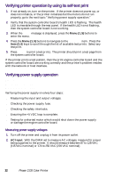
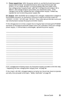
3. Power supply fans: With the power switch on, are the front and rear power supply fans running? (Access the fans by removing the front and rear covers.) If not, check the fans' wiring harnesses (CN2 and CN5) to the low-voltage power supply board; each fan's voltage should measure 32 to 38VDC (the voltage drops to zero when you disconnect a fan). If the voltage is not correct, replace the low-voltage power supply. Otherwise, replace the non-functioning power supply fan. DC Output: With the DMM set to measure DC voltages, measure the voltages at the POWER connector on the bottom of the print engine controller board for +3.3VDC, +5 VDC, +12 VDC and +32 VDC. (You must remove the rear cover and rear shield plate to access the engine controller board.) If the voltages are not correct, inspect the wiring harness connecting the POWER connector of the engine controller board to the CN1 connector of the low-voltage power supply. If the harness is undamaged, replace the power supply. POWER connector pinout Pin Voltage/Signal Level Pin 1 +12 VDC 16 2 No connection 17 3 Ground 18 4 Ground 19 5 Ground 20 6 Ground 21 7 +32 VDC 22 8 +32 VDC 23 9 +32 VDC 24 10 +32 VDC 25 11 +5 VDC 26 12 +5 VDC 27 13 +5 VDC 28 14 +5 VDC 29 15 +3.3 VDC 30 Voltage/Signal Level +3.3 VDC +3.3 VDC +3.3 VDC No connection Signal Signal Signal Signal Signal Ground Ground Ground Ground Signal Signal If DC voltages are not being output by the power supply, proceed to the next step, "Inspecting the low-voltage power supply fuse" on page 34. If the +5 and +32 VDC voltages measure correctly, but the printer does not operate correctly, then proceed to the topic, "Safety interlocks" on page 34. Service Guide 33
-
 1
1 -
2
-
3
-
4
-
5
-
6
-
7
-
8
-
9
-
10
-
11
-
12
-
13
-
14
-
15
-
16
-
17
-
18
-
19
-
20
-
21
-
22
-
23
-
24
-
25
-
26
-
27
-
28
-
29
-
30
-
31
-
32
-
33
-
34
-
35
-
36
-
37
-
38
-
39
-
40
-
 41
41 -
 42
42 -
 43
43 -
 44
44 -
 45
45 -
 46
46 -
 47
47 -
 48
48 -
 49
49 -
 50
50 -
 51
51 -
52
-
53
-
54
-
55
-
56
-
57
-
58
-
59
-
60
-
61
-
62
-
63
-
64
-
65
-
66
-
67
-
68
-
69
-
70
-
71
-
72
-
73
-
74
-
75
-
76
-
77
-
78
-
79
-
80
-
81
-
82
-
83
-
84
-
85
-
86
-
87
-
88
-
89
-
90
-
91
-
92
-
93
-
94
-
95
-
96
-
97
-
98
-
99
-
100
-
101
-
102
-
103
-
104
-
105
-
106
-
107
-
108
-
109
-
110
-
111
-
112
-
113
-
114
-
115
-
116
-
117
-
118
-
119
-
120
-
121
-
122
-
123
-
124
-
125
-
126
-
127
-
128
-
129
-
130
-
131
-
132
-
133
-
134
-
135
-
136
-
137
-
138
-
139
-
140
-
141
-
142
-
143
-
144
-
145
-
146
-
147
-
148
-
149
-
150
-
151
-
152
-
153
-
154
-
155
-
156
-
157
-
158
-
159
-
160
-
161
-
162
-
163
-
164
-
165
-
166
-
167
-
168
-
169
-
170
-
171
-
172
-
173
-
174
-
175
-
176
-
177
-
178
-
179
-
180
-
181
-
182
-
183
-
184
-
185
-
186
-
187
-
188
-
189
-
190
-
191
-
192
-
193
-
194
-
195
-
196
-
197
-
198
-
199
 |
 |
