Asus P5AD2-E Premium User Guide - Page 48
SEC_RAID1 [red]
 |
View all Asus P5AD2-E Premium manuals
Add to My Manuals
Save this manual to your list of manuals |
Page 48 highlights
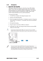
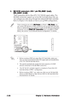
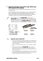
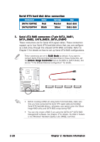
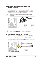
3 . IDE RAID connectors (40-1 pin PRI_RAID1 [red], SEC_RAID1 [red]) These connectors are for Ultra ATA 133/100/66 signal cables. The IDE RAID connectors support up to four IDE hard disk drives that you can configure as a disk array through the onboard IDE RAID controller. Refer to Chapter 5 for details on how to set up RAID configurations. These connectors are set to I D E M o d e by default. In I D E M o d e, you can connect IDE devices to these connectors such as boot/data hard disk drives or optical drives. If you intend to create an IDE RAID set using these connectors, set the I T E 8 2 1 2 F C o n t r o l l e r item in the BIOS to [RAID Mode]. See section "4.4.6 Onboard Devices Configuration" for details. P5AD2-E PREMIUM SEC_RAID1 NOTE: Orient the red markings ® (usually zigzag) on the IDE cable to PIN 1. PRI_RAID1 PIN 1 P5AD2-E PREMIUM RAID connectors • Before creating a RAID set using Ultra ATA hard disks, make sure that you have connected the Ultra ATA signal cable and installed Ultra ATA 133/100/66 hard disk drives. • The system automatically assigns the boot sequence of ATAPI devices connected to the IDE RAID connectors. • The ITE® 8212F controller supports a maximum of two Ultra ATA hard disk drives in RAID 1 configuration. • Before creating a RAID 1 set, make sure that you set the hard disk drives as either Master or Slave device. Refer to the hard disk drive documentation for details. 2-26 Chapter 2: Hardware information
-
 1
1 -
2
-
3
-
4
-
5
-
6
-
7
-
8
-
9
-
10
-
11
-
12
-
13
-
14
-
15
-
16
-
17
-
18
-
19
-
20
-
21
-
22
-
23
-
24
-
25
-
26
-
27
-
28
-
29
-
30
-
31
-
32
-
33
-
34
-
35
-
36
-
37
-
38
-
39
-
40
-
41
-
42
-
 43
43 -
 44
44 -
 45
45 -
 46
46 -
 47
47 -
 48
48 -
 49
49 -
 50
50 -
 51
51 -
 52
52 -
 53
53 -
54
-
55
-
56
-
57
-
58
-
59
-
60
-
61
-
62
-
63
-
64
-
65
-
66
-
67
-
68
-
69
-
70
-
71
-
72
-
73
-
74
-
75
-
76
-
77
-
78
-
79
-
80
-
81
-
82
-
83
-
84
-
85
-
86
-
87
-
88
-
89
-
90
-
91
-
92
-
93
-
94
-
95
-
96
-
97
-
98
-
99
-
100
-
101
-
102
-
103
-
104
-
105
-
106
-
107
-
108
-
109
-
110
-
111
-
112
-
113
-
114
-
115
-
116
-
117
-
118
-
119
-
120
-
121
-
122
-
123
-
124
-
125
-
126
-
127
-
128
-
129
-
130
-
131
-
132
-
133
-
134
-
135
-
136
-
137
-
138
-
139
-
140
-
141
-
142
-
143
-
144
-
145
-
146
-
147
-
148
-
149
-
150
-
151
-
152
-
153
-
154
-
155
-
156
-
157
-
158
-
159
-
160
-
161
-
162
-
163
-
164
-
165
-
166
 |
 |